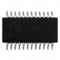
PI3V512QE Pericom Semiconductor, PI3V512QE Datasheet - Page 4

PI3V512QE
Manufacturer Part Number
PI3V512QE
Description
IC 2:1 MUX/DEMUX SW 5PORT 24QSOP
Manufacturer
Pericom Semiconductor
Datasheet
1.PI3V512QE.pdf
(8 pages)
Specifications of PI3V512QE
Function
Video Multiplexer/Demultiplexer
Circuit
5 x 2:1
On-state Resistance
8 Ohm
Voltage Supply Source
Single Supply
Voltage - Supply, Single/dual (±)
3 V ~ 3.6 V
Current - Supply
800µA
Operating Temperature
-40°C ~ 85°C
Mounting Type
Surface Mount
Package / Case
24-QSOP
Number Of Channels
5 Channel
On Resistance (max)
8 Ohms @ 3.3 V @ - 40 C to 85 C
Propagation Delay Time
0.25 ns (Typ)
On Time (max)
15 ns
Off Time (max)
9 ns
Supply Voltage (max)
3.6 V
Supply Voltage (min)
3 V
Maximum Power Dissipation
500 mW
Maximum Operating Temperature
+ 85 C
Minimum Operating Temperature
- 40 C
Mounting Style
SMD/SMT
Lead Free Status / RoHS Status
Lead free / RoHS Compliant
Available stocks
Company
Part Number
Manufacturer
Quantity
Price
Company:
Part Number:
PI3V512QE
Manufacturer:
PERICOM
Quantity:
25
Part Number:
PI3V512QE
Manufacturer:
PERICOM
Quantity:
20 000
Company:
Part Number:
PI3V512QEX
Manufacturer:
TOSHIBA
Quantity:
40 492
Part Number:
PI3V512QEX
Manufacturer:
PERICOM
Quantity:
20 000
Dynamic Electrical Characteristics Over the Operating Range
V CC =3.3V±10%, GND=0V)
Switching Characteristics
Notes:
1. For max. or min. conditions, use appropriate value specified under Electrical Characteristics for the applicable device type.
2. Guaranteed by design.
3. The bus switch contributes no propagational delay other than the RC delay of the On-Resistance of the switch and the load capacitance. The time constant for
Bandwidth vs. Capacitance
X
O
BW
t
t
t
t
t
Parameter
Paramenter
PD
PZH
PHZ
SK(o)
SK(p)
the switch alone is of the order of 0.25ns for 10pF load. Since this time constant is much smaller than the rise/fall times of typical driving signals, it adds very
little propagational delay to the system. Propagational delay of the bus switch when used in a system is determined by the driving circuit on the driving side of
the switch and its interactions with the load on the driven side.
TALK
IRR
, t
, t
PZL
PLZ
10-0250
Propagation Delay
Line Enable Time - SEL to Y
Line Disable Time - SEL to Y
Output Skew between center port (YC to YD) to any other port
Skew between opposite transitions of the same output (t
Description
Crosstalk
OFF Isolation
Bandwidth –3dB
Description
700
600
500
400
300
200
100
0
0 pf
(2,3)
N
N
10 pf
, I
, I
N
N
See Test Diagram (f = 10 MHz)
See Test Diagram (C
Test Conditions
Capacitance Load
20 pf
4
Low On-Resistance, 3.3V Wideband/Video Switch
30 pf
PHL
L
= 0 pF)
- t
PLH
(2)
40 pf
)
(2)
-
-
-
Min.
(T A =-40º to +85ºC,
-
0.5
0.5
-
-
Min.
50 pf
-65
-70
600
Typ.
5-Port 2:1 Mux/DeMux
(2)
0.25
-
-
0.1
0.1
Typ.
(2)
-
-
-
Max.
PS8752C
15
9
0.2
0.2
Max.
PI3V512
dB
MHz
Units
ns
Units
02/16/11


