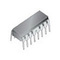
TC4017BP Toshiba, TC4017BP Datasheet

TC4017BP
Specifications of TC4017BP
Available stocks
Related parts for TC4017BP
TC4017BP Summary of contents
Page 1
... TOSHIBA CMOS Digital Integrated Circuit Silicon Monolithic TC4017BP,TC4017BF TC4017BP/TC4017BF Decade Counter/Divider TC4017BP/BF is decimal Johnson counter consisting of 5 stage D-type flip-flop equipped with the decoder to convert the output to decimal. Depending on the number of count pulses fed to CLOCK or CLOCK INHIBIT one output among 10 output lines “Q0” through “ ...
Page 2
... Logic Diagram Timing Chart 2 TC4017BP/BF 2007-10-01 ...
Page 3
... The operating ranges must be maintained to ensure the normal operation of the device. Unused inputs must be tied to either V Symbol Rating − 0.5 − 0.5 − 0.5 OUT SS DD ± 300 (DIP)/180 (SOIC) D −40~85 T opr −65~150 T stg Symbol Test Condition ⎯ ⎯ TC4017BP/BF Unit °C °C Min Typ. Max Unit ⎯ ⎯ 2007-10-01 ...
Page 4
... V, 13.5 V ⎯ 15 4.0 ⎪ < 1 μA ⎯ 18 0.1 ⎯ −0.1 18 ⎯ ⎯ (Note) ⎯ TC4017BP/BF 25°C 85°C Min Typ. Max Min Max ⎯ ⎯ 4.95 5.00 4.95 ⎯ ⎯ 9.95 10.00 9.95 ⎯ ⎯ 14.95 15.00 14.95 ⎯ ⎯ 0.00 ...
Page 5
... THL t pLH ⎯ t pHL t pLH ⎯ t pHL t pLH ⎯ t pHL ⎯ ⎯ ⎯ rCL ⎯ t fCL ⎯ ⎯ t rem ⎯ TC4017BP/ pF) L Min Typ. Max Unit V (V) DD ⎯ 200 ⎯ 100 ns ⎯ ⎯ 200 ⎯ 100 ns ⎯ ⎯ 5 325 650 ⎯ ...
Page 6
... Waveforms for Measurement of Dynamic Characteristics Waveform 1 Waveform 2 Waveform 3 6 TC4017BP/BF 2007-10-01 ...
Page 7
... Package Dimensions Weight: 1.00 g (typ.) 7 TC4017BP/BF 2007-10-01 ...
Page 8
... Package Dimensions Weight: 0.18 g (typ.) 8 TC4017BP/BF 2007-10-01 ...
Page 9
... Please contact your TOSHIBA sales representative for details as to environmental matters such as the RoHS compatibility of Product. Please use Product in compliance with all applicable laws and regulations that regulate the inclusion or use of controlled substances, including without limitation, the EU RoHS Directive. TOSHIBA assumes no liability for damages or losses occurring as a result of noncompliance with applicable laws and regulations. 9 TC4017BP/BF 2007-10-01 ...


