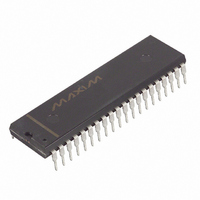
DS2180A Maxim Integrated Products, DS2180A Datasheet - Page 19

DS2180A
Manufacturer Part Number
DS2180A
Description
IC TRANSCEIVER T1 40-DIP
Manufacturer
Maxim Integrated Products
Datasheet
1.DS2180A.pdf
(35 pages)
Specifications of DS2180A
Function
Transceiver
Interface
T1
Number Of Circuits
1
Voltage - Supply
4.5 V ~ 5.5 V
Current - Supply
3mA
Operating Temperature
0°C ~ 70°C
Mounting Type
Through Hole
Package / Case
40-DIP (0.600", 15.24mm)
Includes
Alarm Generation and Detection, B7 Stuffing Mode, B8ZS Mode, Error Detection and Counter, "Hardware" Mode, Transparent Mode
Lead Free Status / RoHS Status
Contains lead / RoHS non-compliant
Power (watts)
-
Available stocks
Company
Part Number
Manufacturer
Quantity
Price
Part Number:
DS2180A
Manufacturer:
DALLAS
Quantity:
20 000
Company:
Part Number:
DS2180A+
Manufacturer:
Exar
Quantity:
207
Company:
Part Number:
DS2180AQ
Manufacturer:
DALLAS
Quantity:
5 510
Part Number:
DS2180AQ
Manufacturer:
DALLAS
Quantity:
20 000
Company:
Part Number:
DS2180AQ+
Manufacturer:
Maxim Integrated Products
Quantity:
135
Company:
Part Number:
DS2180AQ+
Manufacturer:
Maxim
Quantity:
24
Company:
Part Number:
DS2180AQ+T&R
Manufacturer:
Maxim Integrated
Quantity:
10 000
RIMR: RECEIVE INTERRUPT MASK REGISTER Figure 18
(MSB)
ALARM COUNTERS
The three onboard alarm event counters allow the transceiver to monitor and record error events without
processor intervention on each event occurrence. All of these counters are presettable by the user
establishing an event count interrupt threshold. As each counter saturates, the next error event occurrence
will set a bit in the RSR and generate an interrupt unless masked. The user may read these registers at any
time; in many systems, the host will periodically poll these registers to establish link error rate
performance.
OOF EVENTS AND ERRORED
SUPERFRAMES
Out of frame is declared when at least two of four (or five) consecutive framing bits are in error. F
are tested for OOF occurrence in 193S; the FPS bits are tested in 193E. OOF events are recorded by the
4-bit OOF counter in the error counter register. In the 193E framing mode, the OOF event is logically
OR’ed with an on-chip generated CRC checksum. This event, known as errored superframe, is recorded
by the 4-bit ESF error counter in the error count register. In the 193S framing mode, the 4-bit ESF error
counter records individual F
SYMBOL
BVCS
B8ZSD
BVCS
RYEL
RLOS
FERR
RCL
RBL
ECS
ECS
POSITION
RIMR.7
RIMR.6
RIMR.5
RIMR.4
RIMR.3
RIMR.2
RIMR.1
RIMR.0
T
RYEL
and F
S
errors when RCR.3=1 or F
NAME AND DESCRIPTION
Bipolar Violation Count Saturation Mask.
1 = Interrupt masked.
0 = Interrupt masked.
Error Count Saturation Mask.
1 = Interrupt enabled.
0 = Interrupt masked.
Receive Yellow Alarm Mask.
1 = Interrupt enabled.
0 = Interrupt masked.
Receive Carrier Loss Mask.
1 = Interrupt enabled.
0 = Interrupt masked.
Frame Bit Error Mask.
1 = Interrupt enabled.
0 = Interrupt masked.
B8ZS Detect Mask.
1 = Interrupt enabled.
0 = Interrupt masked.
Receive Blue Alarm Mask.
1 = Interrupt enabled.
0 = Interrupt masked.
Receive Loss of Sync Mask.
1 = Interrupt enabled.
0 = Interrupt masked.
RCL
19 of 35
FERR
T
errors only when RCR.3=0.
B8ZSD
RBL
(LSB)
RLOS
DS2180A
T
bits


