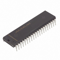
DS2180A Maxim Integrated Products, DS2180A Datasheet - Page 25

DS2180A
Manufacturer Part Number
DS2180A
Description
IC TRANSCEIVER T1 40-DIP
Manufacturer
Maxim Integrated Products
Datasheet
1.DS2180A.pdf
(35 pages)
Specifications of DS2180A
Function
Transceiver
Interface
T1
Number Of Circuits
1
Voltage - Supply
4.5 V ~ 5.5 V
Current - Supply
3mA
Operating Temperature
0°C ~ 70°C
Mounting Type
Through Hole
Package / Case
40-DIP (0.600", 15.24mm)
Includes
Alarm Generation and Detection, B7 Stuffing Mode, B8ZS Mode, Error Detection and Counter, "Hardware" Mode, Transparent Mode
Lead Free Status / RoHS Status
Contains lead / RoHS non-compliant
Power (watts)
-
Available stocks
Company
Part Number
Manufacturer
Quantity
Price
Part Number:
DS2180A
Manufacturer:
DALLAS
Quantity:
20 000
Company:
Part Number:
DS2180A+
Manufacturer:
Exar
Quantity:
207
Company:
Part Number:
DS2180AQ
Manufacturer:
DALLAS
Quantity:
5 510
Part Number:
DS2180AQ
Manufacturer:
DALLAS
Quantity:
20 000
Company:
Part Number:
DS2180AQ+
Manufacturer:
Maxim Integrated Products
Quantity:
135
Company:
Part Number:
DS2180AQ+
Manufacturer:
Maxim
Quantity:
24
Company:
Part Number:
DS2180AQ+T&R
Manufacturer:
Maxim Integrated
Quantity:
10 000
193S FRAMING FORMAT Table 8
NOTES:
1. F
2. F
3. The S-bit in frame 12 may be used for yellow alarm transmission and detection in some applications.
4. The user may program any individual channels clear, in which case bit 8 will be used for data, not
Line Coding
T1 line data is transmitted in a bipolar alternative mark inversion line format; 1’s are transmitted as
alternating negative and positive pulses and 0’s are simply the absence of pulses. This technique
minimizes DC voltage on the T1 span and allows clock to be extracted from data. The network currently
has a 1’s density constraint to keep clock extraction circuitry functioning which is usually met by forcing
bit 7 of any channel consisting of all 0’s to 1. The use of Bipolar Eight Zero Substitution (B8ZS) satisfies
all the 1’s density requirement while allowing data traffic to be transmitted without corruption. This
feature is known as clear channel and is explained more completely in ATT C.B. #144. When the B8ZS
feature is enabled, any outgoing stream of eight consecutive 0’s is replaced with a B8ZS code word. If the
last 1 transmitted was positive, the inserted code is 000+-0-+; if negative, the code word inserted is 000-
+0+-. Bipolar violations occur in the fourth and seventh bit positions which are ignored by the DS2180A
error monitoring logic when B8ZS is enabled. Any received B8ZS code word is replaced with all 0’s if
B8ZS is enabled. Also, the receive status register will report any occurrence of B8ZS code words to the
host controller. This allows the user to monitor the link for upgrade to clear channel capability and
respond to it. The B8ZS monitoring feature works at all times and is independent of the state of CCR.2.
TRANSMIT SIDE OVERVIEW
The transmit side of the DS2180A is made up of six major functional blocks: timing and clock
generation, data selector, bipolar coder, yellow alarm, F-bit data and CRC. The timing and clock
generation circuit develops all onboard and output clocks to the system from inputs TCLK, TFSYNC, and
TMSYNC. The yellow alarm circuitry generates mode–dependent yellow alarms. The CRC block
generates checksum results utilized in 193E framing. F-bit data provides mode–dependent framing
patterns and allows insertion of link or S-bit data externally. All of these blocks feed into the data
selector where, under control of the CCR, TCR, TIRs and TTRs, the contents of the outgoing data stream
are established by bit selection and insertion. The bipolar coder formats the output of the data selector to
NUMBER
FRAME
signaling.
10
11
12
T
S
1
2
3
4
5
6
7
8
9
(terminal framing) bits provide frame alignment information.
(signaling frame) bits provide multiframe alignment information.
F
1
0
1
0
1
0
-
-
-
-
-
-
T
F-BIT USE
1
F
0
0
0
1
1
1
-
-
-
-
-
-
S
3
2
BITS 1-8
BITS 1-8
BITS 1-8
BITS 1-8
BITS 1-7
BITS 1-8
BITS 1-8
BITS 1-8
BITS 1-8
BITS 1-8
BITS 1-7
BITS 1-8
DATA
BIT USE IN EACH CHANNEL
25 of 35
SIGNALING
BIT 8
BIT 8
4
SIGNALING-BIT USE
A
B
DS2180A


