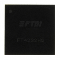
FT4232HQ - REEL FTDI, Future Technology Devices International Ltd, FT4232HQ - REEL Datasheet - Page 43

FT4232HQ - REEL
Manufacturer Part Number
FT4232HQ - REEL
Description
IC USB UART/MPSSE QUAD HS 64-QFN
Manufacturer
FTDI, Future Technology Devices International Ltd
Series
USBmadeEZ-FIFOr
Datasheet
1.FT4232HL_-_REEL.pdf
(45 pages)
Specifications of FT4232HQ - REEL
Features
USB to UART and/or SPI, I2C, JTAG
Number Of Channels
4, QUART
Fifo's
2048 Byte
Protocol
RS-232, RS-422, RS-485
Voltage - Supply
3 V ~ 3.6 V
With Auto Flow Control
Yes
With Modem Control
Yes
With Cmos
Yes
Mounting Type
Surface Mount
Package / Case
64-QFN
For Use With
768-1031 - MOD USB HS FT4232H EVAL
Lead Free Status / RoHS Status
Lead free / RoHS Compliant
Other names
768-1027-2
FT4232HQ - REEL
FT4232HQ - REEL
Document No.: FT_000060
FT4232H QUAD HIGH SPEED USB TO MULTIPURPOSE UART/MPSSE IC
Datasheet Version 2.10
Clearance No.: FTDI#78
Appendix A - List of Figures and Tables
List of Tables
Table 3.1 FT4232H Pin Configurations ....................................................................................... 9
Table 3.2 Power and Ground ........................................................................................................ 10
Table 3.3 Common Function pins .................................................................................................. 11
Table 3.4 EEPROM Interface Group ............................................................................................... 11
Table 3.5 Channel A,B,C and Channel D Asynchronous Serial Interface Configured Pin Descriptions ...... 12
Table 3.6 Channel A,B,C and Channel D Synchronous or Asynchronous Bit-Bang Configured Pin
Descriptions ............................................................................................................................. 13
Table 3.7 Channel A and Channel B MPSSE Configured Pin Descriptions .................................. 14
Table 4.1 MPSSE Signal Timings ................................................................................................... 20
Table 4.2 Synchronous Bit-Bang Mode Timing Interface Example Timings .......................................... 23
Table 5.1 Absolute Maximum Ratings ............................................................................................ 25
Table 5.2 Operating Voltage and Current ....................................................................................... 26
Table 5.3 I/O Pin Characteristics (except USB PHY pins) .................................................................. 27
Table 5.4 PHY Operating Voltage and Current ................................................................................. 28
Table 5.5 PHY I/O Pin Characteristics ............................................................................................ 28
Table 5.6 ESD Tolerance .............................................................................................................. 28
Table 6.1 OSCI Input characteristics ............................................................................................. 33
Table 8.1 64 pin LQFP Package Details – dimensions (in mm)........................................................... 39
Table 8.2 Reflow Profile Parameter Values ..................................................................................... 41
Table 8.3 Package Reflow Peak Temperature .................................................................................. 41
List of Figures
Figure 2.1 FT4232H Block Diagram ................................................................................................. 4
Figure 3.1 FT4232H Schematic Symbol ............................................................................................ 7
Figure 4.1 RS232 Configuration .................................................................................................... 17
Figure 4.2 Dual RS422 Configuration ............................................................................................. 18
Figure 4.3 Dual RS485 Configuration ............................................................................................. 19
Figure 4.4 MPSSE Signal Waveforms ............................................................................................. 20
Figure 4.5 Adaptive Clocking Interconnect ..................................................................................... 21
Figure 4.6: Adaptive Clocking waveform. ....................................................................................... 21
Figure 4.7 Synchronous Bit-Bang Mode Timing Interface Example .................................................... 23
Figure 6.1 Bus Powered Configuration Example 1............................................................................ 29
Figure 6.2 Bus Powered Configuration Example 2............................................................................ 30
Figure 6.3 Self Powered Configuration Example 1 ........................................................................... 31
Figure 6.4 Self Powered Configuration Example 2 ........................................................................... 32
Figure 6.5 Recommended FT4232H Crystal Oscillator Configuration. ................................................. 33
Figure 6.6 Using 74HCT595 to Indicate Tx and Rx Data ................................................................... 34
Figure 8.1 64 pin QFN Package Details .......................................................................................... 37
Figure 8.2 64 pin LQFP Package Details ......................................................................................... 38
Copyright © 2010 Future Technology Devices International Limited
43


