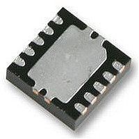
AS1705V austriamicrosystems, AS1705V Datasheet - Page 14

AS1705V
Manufacturer Part Number
AS1705V
Description
IC AMP AUDIO MONO 1.8W 10-DFN
Manufacturer
austriamicrosystems
Type
Class ABr
Datasheet
1.AS1702.pdf
(20 pages)
Specifications of AS1705V
Output Type
1-Channel (Mono)
Max Output Power X Channels @ Load
1.8W x 1 @ 4 Ohm
Voltage - Supply
2.7 V ~ 5.5 V
Features
Depop, Differential Inputs, Short-Circuit and Thermal Protection, Shutdown
Mounting Type
Surface Mount
Package / Case
10-TDFN Exposed Pad
No. Of Channels
1
Output Power
1.8W
Supply Voltage Range
2.7V To 5.5V
Load Impedance
4ohm
Operating Temperature Range
-40°C To +85°C
Amplifier Case Style
DFN
No. Of Pins
10
Rohs Compliant
Yes
Lead Free Status / RoHS Status
Lead free / RoHS Compliant
AS1702 - AS1705
Data Sheet
If the internal power dissipation exceeds the maximum allowed for a given package, power dissipation should be
reduced by increasing the ground plane heat-sinking capabilities and increasing the size of the device traces
out and Grounding Considerations on page
ing ambient temperature can reduce device power dissipation.
The integrated thermal-overload protection circuitry limits the total device power dissipation. Note that if the junction
temperature is ≥ +145ºC, the integrated thermal-overload protection circuitry will disable the amplifier output stage. If
the junction temperature is reduced by 9°, the amplifiers will be re-enabled.
Note: A pulsing output under continuous thermal overload results as the device heats and cools.
Fixed Differential Gain (AS1703
The AS1703, AS1704, and AS1705 contain different internally-fixed gains
fixed gain facilitates simplified designs, decreased footprint size, and elimination of external gain-setting resistors.
The fixed gain values are achieved using resistors R
Adjustable Differential Gain (AS1702)
Gain-Setting Resistors
The AS1702 uses external feedback resistors, R
where A
Note: R
Figure 33. Setting the AS1702 Gain
www.austriamicrosystems.com
tiometer. For more information on the AS1500 family of digital potentiometers, refer to the latest version of the
AS150x data sheet , available from the austriamicrosystems website http://www.austriamicrosystems.com.)
V
F
is the desired voltage gain. For example, R
can be either fixed or variable, allowing the gain to be controlled by software (using a AS150x digital poten-
- A p p l i c a t i o n I n f o r m a t i o n
Differential Input
Differential Input
Non-Inverting
Inverting
* Optional
10µF
10µF
C
C
IN
IN
*
*
0.1µF
C
BIAS
10kΩ
10kΩ
R
R
IN
IN
15). Additionally, reducing V
,
AS1704, and AS1705)
BIAS
IN+
IN-
F
2
4
5
and R
1
Revision 1.47
IN
and R
= 10kΩ, R
A
IN
V
Generator
(Figure
=
Bias
2
(see Figure 31 on page
R
R
IN
F
F
33), to set the gain of the device as:
= 20kΩ yields a gain of 2V/V, or 6dB.
20kΩ
20kΩ
R
R
F
F
–
+
CC
AS1702
(see Ordering Information on page
, increasing load impedance, and decreas-
12).
10
OUT+
6
OUT-
(see Lay-
19). A
(EQ 7)
14 - 20


