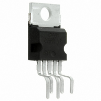
E-TDA2003H STMicroelectronics, E-TDA2003H Datasheet

E-TDA2003H
Specifications of E-TDA2003H
Related parts for E-TDA2003H
E-TDA2003H Summary of contents
Page 1
... The device provides a high output current capability (up to 3.5A) very low harmonic and cross-over distortion. Completely safe operation is guaranteed due to protection against DC and AC short circuit between all pins and ground, thermal over-range, load dump voltage surge up to 40V and fortuitous open ground. ...
Page 2
... TDA2003 PIN CONNECTION (top view) SCHEMATIC DIAGRAM THERMAL DATA Symbol R Thermal resistance junction-case th-j-case 2/10 Parameter Value Unit max 3 C/W ...
Page 3
... ELECTRICAL CHARACTERISTICS ( V Symbol Parameter DC CHARACTERISTICS (Refer to DC test circuit) V Supply voltage s V Quiescent output voltage (pin Quiescent drain current (pin CHARACTERISTICS (Refer to AC test circuit dB) P Output power o V Input saturation voltage i(rms) V Input sensitivity i AC TEST CIRCUIT = 14.4V unless otherwise specified) ...
Page 4
... R Input resistance (pin Voltage gain (open loop Voltage gain (closed loop Input noise voltage N i Input noise current N Efficiency SVR Supply voltage rejection (0) Filter with noise bandwidth kHz Figure 1. Quiescent output voltage vs. supply voltage 4/10 Test conditions kHz P = 0.05 to4. 0.05 to 7.5W R ...
Page 5
... Figure 4. Output power vs. load resistance ure 7. Di stortion vs. output power Figure 10. Supply voltage rejection vs. frequency Figure 5. Gain vs. input sensivity Fi gure 8. Distor tion vs. frequency Figure 11. Power dissipa- tion and efficiency vs. output power ( TDA2003 Figure 6. Gain vs. input sensivity Figure 9. Supply voltage rejection vs. voltage gain Figure 12 ...
Page 6
... A suggested LC network is shown in fig. 19. With this network, a train of pulses with amplitude up to 120V and width can be applied at point A. This type of protection is ON when the supply voltage (pulsed or DC) exceeds 18V. For this reason the maximum operating supply voltage is 18V. ...
Page 7
... Figure 18. Short-circuit (AC and DC conditions) The TDA 2003 can withstand a permanent short- circuit on the output for a supply voltage up to 16V. Polarity inversion High current (up to 5A) can be handled by the device with no damage for a longer period than the blow-out time of a quick 1A fuse (normally con- nected in series with the supply) ...
Page 8
... PRATICAL CONSIDERATION Printed circuit board The layout shown in fig recommended. If different layouts are used, the ground points of input 1 and input 2 must be well decoupled from the ground of the output through which a rather high current flows. Assembly suggestion No electrical insulation is required between the ...
Page 9
... RESIN BETWEEN LEADS TDA2003 OUTLINE AND MECHANICAL DATA Pentawatt 9/10 ...
Page 10
... STMicroelectronics. © 1998 STMicroelectronics – Printed in Italy – All Rights Reserved Australia - Brazil - Canada - China - France - Germany - Italy - Japan - Korea - Malaysia - Malta - Mexico - Morocco - The Netherlands - Singapore - Spain - Sweden - Switzerland - Taiwan - Thailand - United Kingdom - U.S.A. ...


