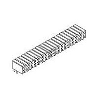
4-1734531-8 TE Connectivity, 4-1734531-8 Datasheet - Page 2

4-1734531-8
Manufacturer Part Number
4-1734531-8
Description
Manufacturer
TE Connectivity
Specifications of 4-1734531-8
Product Type
Connector
Connector Type
Connector Assembly
Pcb Mount Style
Through Hole
Shrouded
No
Pcb Mount Retention
Without
Pcb Mounting Orientation
Right Angle
Keyed
No
Holddown Feature
Without
Post Size (mm [in])
0.50 [.020]
Voltage (vac)
200
Contact - Rated Current (a)
1
Insulation Resistance (m?)
1,000
Termination Post Length (mm [in])
3.00 [0.118]
Solder Tail Contact Plating
Tin over Nickel
Centerline (mm [in])
2.00 [0.079]
Number Of Positions
48
Selectively Loaded
No
Post Number(s) Omitted
None
Centerline, Matrix (mm [in])
2.00 x 2.00 [.079 x .079]
Mating Pin-to-pcb Dimension (mm [in])
1.50 [0.059]
Mount Type
Printed Circuit Board
Number Of Rows
Dual
Cover
Without
Contact Plating, Mating Area, Material
Gold (10)
Contact Base Material
Phosphor Bronze
Connector Style
Receptacle
Housing Material
Thermoplastic - GF
Dielectric Strength (vac)
650
Ul Flammability Rating
UL 94V-0
Housing Color
Black
Housing Entry Style
Closed Top
Stack Height (mm [in])
4.85 [0.191]
Rohs/elv Compliance
RoHS compliant, ELV compliant
Lead Free Solder Processes
Wave solder capable to 240°C, Wave solder capable to 260°C, Wave solder capable to 265°C
Rohs/elv Compliance History
Always was RoHS compliant
Approved Standards
UL E28476, CSA LR7189
Temperature Range (°c)
-40 – +105
Pcb Thickness, Recommended (mm [in])
1.57 [0.062]
Packaging Method
Tube
3.5.2.1
3.5.2.2
3.5.2.3
3.5.3.1
3.5.3.2
3.5.3.3
3.5.3.4
Rev
3.5.1
NO.
3.3. RATINGS
3.4. PERFOMANCE AND TEST DESCRIPTION
3.5. TEST REQUIREMENTS AND PROCEDURES SUMMARY
B
A. Voltage: 250 VAC rms.
B. Current: 1 A Max
C. Operating Temperature: -40° C to + 105° C
Examination of
Product
Termination
Resistance
Insulation
Resistance
Dielectric Strength
Individual Pin
Insertion/ Extraction
Force
Receptacle Contact
Retention Force
Post Retention
Force
Solder ability
TEST ITEMS
The product is designed to meet the electrical, mechanical and environmental
performance requirements specified in Table 2. All tests are performed at
ambient environmental conditions per AMP Specification 109-1 unless otherwise
specified.
Meets requirements of product
drawing. No physical damage.
1000M ohms min. (Initial)
1000M ohms min (Final)
Connector must withstand test
potential of 650VAC for 1 min.
Current leakage limit to 5.0mA
max.
250 gf min. per contact
0.5 kgf min. per contact
The inspected area of each lead
must have 95% solder coverage
minimum.
Insertion Force
200 gf max
Initial
Final
MECHANICAL REQUIREMENTS
ELECTRICAL REQUIREMENTS
REQUIREMENTS
20m ohms max.
30m ohms max.
Extraction
10gf min
Force
Visual inspection.
Subject mated contacts assembled in
housing to closed circuit current of 50mA
max at open circuit voltage of 50mV max.
(See Fig. 1)
Measure by applying test potential between
adjacent contacts, and between the
contacts and ground in the mated connector
assembly.
MIL-STD-202, Method 302, Condition B
Measure by applying test potential between
adjacent contacts, and between the
contacts and ground in the mated connector
assembly.
MIL-STD-202, Method 301
Subject terminated contact and pin to mate
and unmate to measure the force required
to insert and extract by operating at a rate of
100mm a minute. (See Fig. 2)
Apply axial load to terminated contact at a
rate of 25mm a minute.
Apply axial pull-off load to post contact
mounted on housing and measure the force
required to dislodge post from housing.
Steam Aging Preconditioning:
(1) Tin、Tin-Cu Coating:
93+3/-5℃、100% HR、8hrs.
<J-STD-002 category 3 aging>
(2) Other Coating:
93+3/-5℃、100% HR、1hrs.
<J-STD-002 category 2 aging>
Solder pot temperature: 245±5℃, 5sec
PROCEDURES
108-57197
2 of 5


