MC74VHC1G50DFT2 ON Semiconductor, MC74VHC1G50DFT2 Datasheet
MC74VHC1G50DFT2
Specifications of MC74VHC1G50DFT2
MC74VHC1G50DFT2OS
MC74VHC1G50DFT2OS
Available stocks


Related parts for MC74VHC1G50DFT2

MC74VHC1G50DFT2 Summary of contents
Page 1
... Chip Complexity: FET = 104; Equivalent Gate = 26 • These devices are available in Pb- -free package(s). Specifications herein apply to both standard and Pb- -free devices. Please see our website at www.onsemi.com for specific Pb- -free orderable part numbers, or contact your local ON Semiconductor sales office or representative GND Figure 1 ...
Page 2
MAXIMUM RATINGS (Note 1) Symbol V DC Supply Voltage Input Voltage Output Voltage OUT I Input Diode Current IK I Output Diode Current Output Current, per Pin OUT I DC Supply ...
Page 3
DC ELECTRICAL CHARACTERISTICS Symbol Parameter Test Conditions V Minimum High--Level IH Input Voltage V Maximum Low--Level IL Input Voltage V Minimum High--Level Output Voltage ...
Page 4
... Y 50 Figure 4. Switching Waveforms DEVICE ORDERING INFORMATION Circuit Indicator Identifier Device Order Number MC74VHC1G50DFT1 MC MC74VHC1G50DFT2 MC MC74VHC1G50DTT1 MC †For information on tape and reel specifications, including part orientation and tape sizes, please refer to our Tape and Reel Packaging Specifications Brochure, BRD8011/ GND t PLH Device Nomenclature ...
Page 5
TAPE TRAILER (Connected to Reel Hub) CAVITY TOP TAPE NO COMPONENTS TAPE 160 mm MIN TAPE DIMENSIONS mm 4.00 2.00 8.00 ±0.30 Figure 7. SC- -70- -5/SC- -88A/SOT- -353 DFT1 Reel Configuration/Orientation TAPE DIMENSIONS mm 4.00 2.00 8.00 ±0.30 Figure ...
Page 6
MIN A (0.795 in) FULL RADIUS Figure 9. Reel Dimensions REEL DIMENSIONS Tape Size T and R Suffix A Max 8 mm T1, T2 178 mm (7 in) DIRECTION OF FEED Figure 10. Reel Winding Direction http://onsemi.com 13.0 ...
Page 7
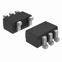
... 0.50 0.0197 0.40 0.0157 Figure 11. *For additional information on our Pb--Free strategy and soldering details, please download the ON Semiconductor Soldering and Mounting Techniques Reference Manual, SOLDERRM/D. PACKAGE DIMENSIONS SC70- -5/SC- -88A/SOT- -353 DF SUFFIX NOTES: 5--LEAD PACKAGE 1. DIMENSIONING AND TOLERANCING CASE 419A--02 PER ANSI Y14.5M, 1982. ...
Page 8
... H Figure 12. *For additional information on our Pb--Free strategy and soldering details, please download the ON Semiconductor Soldering and Mounting Techniques Reference Manual, SOLDERRM/D. ON Semiconductor and are registered trademarks of Semiconductor Components Industries, LLC (SCILLC). SCILLC reserves the right to make changes without further notice to any products herein ...