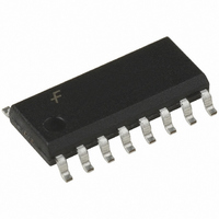
74VHC161M Fairchild Semiconductor, 74VHC161M Datasheet - Page 6

74VHC161M
Manufacturer Part Number
74VHC161M
Description
IC COUNTER BINARY 4BIT 16SOIC
Manufacturer
Fairchild Semiconductor
Series
74VHCr
Type
Binaryr
Datasheet
1.74VHC161MX.pdf
(11 pages)
Specifications of 74VHC161M
Logic Type
Binary Counter
Direction
Up
Number Of Elements
1
Number Of Bits Per Element
4
Reset
Asynchronous
Timing
Synchronous
Count Rate
125MHz
Trigger Type
Positive Edge
Voltage - Supply
2 V ~ 5.5 V
Operating Temperature
-40°C ~ 85°C
Mounting Type
Surface Mount
Package / Case
16-SOIC (3.9mm Width)
Counter Type
Binary
Counting Sequence
Up
Number Of Circuits
1
Logic Family
74VHC
Propagation Delay Time
16.3 ns, 10.1 ns
Supply Voltage (max)
5.5 V
Maximum Operating Temperature
+ 85 C
Minimum Operating Temperature
- 40 C
Function
Counter
Mounting Style
SMD/SMT
Operating Supply Voltage
2.5 V, 3.3 V, 5 V
Technology
CMOS
Number Of Elements
1
Number Of Bits
4
Logical Function
Counter
Operating Supply Voltage (typ)
2.5/3.3/5V
Output Type
Standard
Package Type
SOIC N
Operating Temp Range
-40C to 85C
Operating Supply Voltage (min)
2V
Operating Supply Voltage (max)
5.5V
Operating Temperature Classification
Industrial
Mounting
Surface Mount
Pin Count
16
Lead Free Status / RoHS Status
Lead free / RoHS Compliant
Available stocks
Company
Part Number
Manufacturer
Quantity
Price
Company:
Part Number:
74VHC161M
Manufacturer:
Fairchild Semiconductor
Quantity:
1 869
Part Number:
74VHC161MTCX
Manufacturer:
FAIRCHILD/仙童
Quantity:
20 000
Company:
Part Number:
74VHC161MX
Manufacturer:
FAIRCHILD
Quantity:
50 000
Part Number:
74VHC161MX
Manufacturer:
FAIRCHILD/仙童
Quantity:
20 000
©1993 Fairchild Semiconductor Corporation
74VHC161 Rev. 1.4
AC Electrical Characteristics
Note:
3. C
t
t
t
t
Symbol
PLH
PLH
PLH
PLH
current consumption without load. Average operating current can be obtained by the equation:
I
When the outputs drive a capacitive load, total current consumption is the sum of C
from the following formula:
C
CC
f
PD
Q0
t
t
C
C
MAX
PHL
PHL
, t
, t
, t
, t
PD
IN
(opr) = C
–C
is defined as the value of the internal equivalent capacitance which is calculated from the operating
PHL
PHL
PHL
PHL
Q3
and C
Propagation Delay
Time (CP–Q
Propagation Delay
Time (CP–TC, Count)
Propagation Delay
Time (CP–TC, Load)
Propagation Delay
Time (CET–TC)
Propagation Delay
Time (MR –Q
Propagation Delay
Time (MR –TC)
Maximum Clock
Frequency
Input Capacitance
Power Dissipation
Capacitance
PD
• V
TC
Parameter
CC
are the capacitances at Q0–Q3 and TC, respectively. F
• f
n
IN
)
n
)
+ I
CC
3.3 ± 0.3
5.0 ± 0.5
3.3 ± 0.3
5.0 ± 0.5
3.3 ± 0.3
5.0 ± 0.5
3.3 ± 0.3
5.0 ± 0.5
3.3 ± 0.3
5.0 ± 0.5
3.3 ± 0.3
5.0 ± 0.5
3.3 ± 0.3
5.0 ± 0.5
V
CC
(V)
C
C
C
C
C
C
C
C
C
C
C
C
C
C
C
C
C
C
C
C
C
C
C
C
C
C
C
C
V
(3)
Conditions
L
L
L
L
L
L
L
L
L
L
L
L
L
L
L
L
L
L
L
L
L
L
L
L
L
L
L
L
CC
= 15pF
= 50pF
= 15pF
= 50pF
= 15pF
= 50pF
= 15pF
= 50pF
= 15pF
= 50pF
= 15pF
= 50pF
= 15pF
= 50pF
= 15pF
= 50pF
= 15pF
= 50pF
= 15pF
= 50pF
= 15pF
= 50pF
= 15pF
= 50pF
= 15pF
= 50pF
= 15pF
= 50pF
= Open
6
Min.
135
80
55
95
T
A
CP
Typ.
10.8
11.2
11.0
13.5
10.5
11.2
10.9
= 25°C
130
185
125
8.3
4.9
6.4
8.7
4.9
6.4
6.2
7.7
7.5
4.9
6.4
8.9
5.5
7.0
8.4
5.0
6.5
85
23
is the input frequency of the CP.
4
PD
Max.
12.8
16.3
10.1
13.6
17.1
10.1
17.2
20.7
10.3
12.3
12.3
15.8
10.1
13.6
17.1
11.0
13.2
16.7
10.6
8.1
8.1
8.1
9.0
8.6
10
, and ∆I
T
Min.
115
A
1.0
1.0
1.0
1.0
1.0
1.0
1.0
1.0
1.0
1.0
1.0
1.0
1.0
1.0
1.0
1.0
1.0
1.0
1.0
1.0
1.0
1.0
1.0
1.0
CC
70
50
85
= –40° to
+85°C
which is obtained
Max.
15.0
18.5
11.5
16.0
19.5
11.5
20.0
23.5
12.0
14.0
14.5
18.0
11.5
16.0
19.5
10.5
12.5
15.5
19.0
10.0
12.0
9.5
9.5
9.5
10
www.fairchildsemi.com
Units
MHz
MHz
pF
pF
ns
ns
ns
ns
ns
ns
ns
ns
ns
ns
ns
ns


