DS1248WP-120IND Maxim Integrated Products, DS1248WP-120IND Datasheet - Page 5
DS1248WP-120IND
Manufacturer Part Number
DS1248WP-120IND
Description
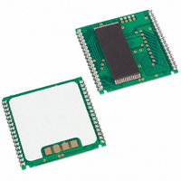
IC NVSRAM 1MBIT 120NS 34PCM
Manufacturer
Maxim Integrated Products
Datasheet
1.DS1248W-120.pdf
(18 pages)
Specifications of DS1248WP-120IND
Format - Memory
RAM
Memory Type
NVSRAM (Non-Volatile SRAM)
Memory Size
1M (128K x 8)
Speed
120ns
Interface
Parallel
Voltage - Supply
3 V ~ 3.6 V
Operating Temperature
-40°C ~ 85°C
Package / Case
34-PowerCap™ Module
Lead Free Status / RoHS Status
Contains lead / RoHS non-compliant


DS1248/DS1248P 1024k NV SRAM with Phantom Clock
PHANTOM CLOCK OPERATION
Communication with the phantom clock is established by pattern recognition on a serial bit stream of
64 bits, which must be matched by executing 64 consecutive write cycles containing the proper data on
DQ0. All accesses that occur prior to recognition of the 64-bit pattern are directed to memory.
After recognition is established, the next 64 read or write cycles either extract or update data in the
phantom clock, and memory access is inhibited.
Data transfer to and from the timekeeping function is accomplished with a serial bit stream under control
of chip enable, output enable, and write enable. Initially, a read cycle to any memory location using the
CE and OE control of the phantom clock starts the pattern recognition sequence by moving a pointer to
the first bit of the 64-bit comparison register. Next, 64 consecutive write cycles are executed using the CE
and WE control of the SmartWatch. These 64 write cycles are used only to gain access to the phantom
clock. Therefore, any address to the memory in the socket is acceptable. However, the write cycles
generated to gain access to the phantom clock are also writing data to a location in the mated RAM. The
preferred
way
to
manage
this
requirement
is
to
set
aside
just
one address location in RAM as a phantom clock scratch pad. When the first write cycle is executed, it is
compared to bit 0 of the 64-bit comparison register. If a match is found, the pointer increments to the next
location of the comparison register and awaits the next write cycle. If a match is not found, the pointer
does not advance and all subsequent write cycles are ignored. If a read cycle occurs at any time during
pattern recognition, the present sequence is aborted and the comparison register pointer is reset. Pattern
recognition continues for a total of 64 write cycles as described above until all the bits in the comparison
register have been matched (Figure 1). With a correct match for 64 bits, the phantom clock is enabled and
data transfer to or from the timekeeping registers can proceed. The next 64 cycles will cause the phantom
clock to either receive or transmit data on DQ0, depending on the level of the OE pin or the WE pin.
Cycles to other locations outside the memory block can be interleaved with CE cycles without
interrupting the pattern recognition sequence or data transfer sequence to the phantom clock.
PHANTOM CLOCK REGISTER INFORMATION
The phantom clock information is contained in eight registers of 8 bits, each of which is sequentially
accessed 1 bit at a time after the 64-bit pattern recognition sequence has been completed. When updating
the phantom clock registers, each register must be handled in groups of 8 bits. Writing and reading
individual bits within a register could produce erroneous results. These read/write registers are defined in
Figure 2.
Data contained in the phantom clock register is in binary-coded decimal format (BCD). Reading and
writing the registers is always accomplished by stepping through all eight registers, starting with bit 0 of
register 0 and ending with bit 7 of register 7.
5 of 18
Related parts for DS1248WP-120IND
Image
Part Number
Description
Manufacturer
Datasheet
Request
R

Part Number:
Description:
IC NVSRAM 1MBIT 120NS 34PCM
Manufacturer:
Maxim Integrated Products
Datasheet:
Part Number:
Description:
IC NVSRAM 1MBIT 120NS 34PCM
Manufacturer:
Maxim Integrated Products
Datasheet:
Part Number:
Description:
IC NVSRAM 1MBIT 120NS 34PCM
Manufacturer:
Maxim Integrated Products
Datasheet:

Part Number:
Description:
The DS1248 1024K NV SRAM with Phantom Clock is a fully static nonvolatile RAM (organized as 128K words by 8 bits) with a built-in real-time clock
Manufacturer:
Maxim
Datasheet:

Part Number:
Description:
MAX7528KCWPMaxim Integrated Products [CMOS Dual 8-Bit Buffered Multiplying DACs]
Manufacturer:
Maxim Integrated Products
Datasheet:
Part Number:
Description:
Single +5V, fully integrated, 1.25Gbps laser diode driver.
Manufacturer:
Maxim Integrated Products
Datasheet:
Part Number:
Description:
Single +5V, fully integrated, 155Mbps laser diode driver.
Manufacturer:
Maxim Integrated Products
Datasheet:
Part Number:
Description:
VRD11/VRD10, K8 Rev F 2/3/4-Phase PWM Controllers with Integrated Dual MOSFET Drivers
Manufacturer:
Maxim Integrated Products
Datasheet:
Part Number:
Description:
Highly Integrated Level 2 SMBus Battery Chargers
Manufacturer:
Maxim Integrated Products
Datasheet:
Part Number:
Description:
Current Monitor and Accumulator with Integrated Sense Resistor; ; Temperature Range: -40°C to +85°C
Manufacturer:
Maxim Integrated Products
Part Number:
Description:
TSSOP 14/A�/RS-485 Transceivers with Integrated 100O/120O Termination Resis
Manufacturer:
Maxim Integrated Products
Part Number:
Description:
TSSOP 14/A�/RS-485 Transceivers with Integrated 100O/120O Termination Resis
Manufacturer:
Maxim Integrated Products
Part Number:
Description:
QFN 16/A�/AC-DC and DC-DC Peak-Current-Mode Converters with Integrated Step
Manufacturer:
Maxim Integrated Products
Part Number:
Description:
TDFN/A/65V, 1A, 600KHZ, SYNCHRONOUS STEP-DOWN REGULATOR WITH INTEGRATED SWI
Manufacturer:
Maxim Integrated Products
Part Number:
Description:
Integrated Temperature Controller f
Manufacturer:
Maxim Integrated Products