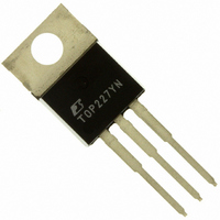
TOP227YN Power Integrations, TOP227YN Datasheet - Page 10

TOP227YN
Manufacturer Part Number
TOP227YN
Description
IC OFFLINE SWIT PWM OCP HV TO220
Manufacturer
Power Integrations
Series
TOPSwitch®-IIr
Type
Off Line Switcherr
Datasheet
1.TOP222GN-TL.pdf
(20 pages)
Specifications of TOP227YN
Output Isolation
Isolated
Frequency Range
90 ~ 110kHz
Voltage - Output
700V
Power (watts)
150W
Operating Temperature
-40°C ~ 150°C
Package / Case
TO-220-3
Output Voltage
5.7 V
Input / Supply Voltage (max)
265 VAC
Input / Supply Voltage (min)
85 VAC
Duty Cycle (max)
70 %
Switching Frequency
100 KHz
Supply Current
1.4 mA
Operating Temperature Range
- 40 C to + 150 C
Mounting Style
Through Hole
Supply Voltage
265VAC
No. Of Pins
3
No. Of Regulated Outputs
1
Filter Terminals
Through Hole
Output Voltage Max
700V
Rohs Compliant
Yes
Operating Temperature Max
150°C
Lead Free Status / RoHS Status
Lead free / RoHS Compliant
Other names
596-1163-5
TOP227YN
TOP227YN
Available stocks
Company
Part Number
Manufacturer
Quantity
Price
Output
Frequency
Maximum
Duty Cycle
Minimum
Duty Cycle
PWM
Gain
PWM Gain
Temperature Drift
External
Bias Current
Dynamic
Impedance
Dynamic Impedance
Temperature Drift
CONTROL Pin
Charging Current
Charging Current
Temperature Drift
10
CONTROL FUNCTIONS
SHUTDOWN/AUTO-RESTART
TOP221-227
DRAIN Voltage ............................................ -0.3 to 700 V
DRAIN Current Increase ( I
blanking time ......................................... 0.1 x I
CONTROL Voltage ..................................... - 0.3 V to 9 V
CONTROL Current ............................................... 100 mA
Storage Temperature ..................................... -65 to 150 C
Notes:
1. All voltages referenced to SOURCE, T
2. Related to transformer saturation – see Figure 13.
3. Normally limited by internal circuitry.
4. 1/16" from case for 5 seconds.
Parameter
D
7/01
Symbol
D
D
D
f
OSC
Z
I
I
) in 100 ns except during
MAX
MIN
B
C
C
ABSOLUTE MAXIMUM RATINGS
SOURCE = 0 V
I
C
A
(Unless Otherwise Specified)
= I
= 25 C.
I
C
CD1
I
I
I
= 10 mA, See Figure 10
LIMIT(MAX)
T
C
C
C
J
+ 0.4 mA, See Figure 10
= 4 mA, T
= 4 mA, T
= 4 mA, T
= 25 C
Conditions
See Figure 14
See Figure 11
See Figure 4
See Figure 4
See Note A
See Note A
(2)
;
T
J
J
J
J
= -40 to 125 C
Operating Junction Temperature
Lead Temperature
Thermal Impedance: Y Package (
5. Free standing with no heatsink.
6. Measured at tab closest to plastic interface or SOURCE pin.
7. Soldered to 0.36 sq. inch (232 mm
8. Soldered to 1 sq. inch (645 mm
= 25 C
= 25 C
= 25 C
V
V
C
C
= 0 V
= 5 V
(4)
................................................ 260 C
(1)
P/G Package:
Min
-2.4
-21
0.7
0.8
90
64
10
-2
(
(
JC
JA
)
) .........45 C/W
(6)
2
-0.05
0.18
), 2 oz. (610 gm/m
Typ
-1.9
-1.5
(3)
100
-16
2
1.7
2.0
0.4
(
...............................11 C/W
67
15
), 2 oz. (610 gm/m
................ -40 to 150 C
JC
JA
)
)
(6)
(5)
...................2 C/W
.................70 C/W
Max
-1.2
-0.8
110
-11
2.7
3.3
70
22
(7)
; 35 C/W
2
2
) copper clad.
) copper clad.
%/mA/ C
Units
%/mA
%/ C
%/ C
kHz
mA
mA
%
%
(8)


