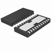
LTC4090EDJC#PBF Linear Technology, LTC4090EDJC#PBF Datasheet - Page 19

LTC4090EDJC#PBF
Manufacturer Part Number
LTC4090EDJC#PBF
Description
IC USB POWER MANAGER 22-DFN
Manufacturer
Linear Technology
Datasheet
1.LTC4090EDJCPBF.pdf
(28 pages)
Specifications of LTC4090EDJC#PBF
Function
Power Management
Battery Type
Lithium-Ion (Li-Ion), Lithium-Polymer (Li-Pol)
Voltage - Supply
4.35 V ~ 5.5 V
Operating Temperature
-40°C ~ 85°C
Mounting Type
Surface Mount
Package / Case
22-WFDFN Exposed Pad
Supply Voltage Range
4.35V To 5.5V
Operating Temperature Range
-40°C To +85°C
Digital Ic Case Style
DFN
No. Of Pins
22
Msl
MSL 1 - Unlimited
Termination Type
SMD
Supply Voltage Min
4.35V
Rohs Compliant
Yes
Filter Terminals
SMD
Frequency
2.7MHz
Lead Free Status / RoHS Status
Lead free / RoHS Compliant
Available stocks
Company
Part Number
Manufacturer
Quantity
Price
APPLICATIONS INFORMATION
minimum switch-off time (~150ns). These equations show
that duty cycle range increases when switching frequency
is decreased.
A good choice of switching frequency should allow ad-
equate input voltage range (see next section) and keep
the inductor and capacitor values small.
HVIN Input Voltage Range
The maximum input voltage range for the LTC4090/
LTC4090-5 applications depends on the switching fre-
quency, the Absolute Maximum Ratings of the V
BOOST pins, and the operating mode.
The high voltage switching regulator can operate from
input voltages up to 36V, and safely withstand input volt-
ages up to 60V. Note that while V
LTC4090/LTC4090-5 will stop switching, allowing the
output to fall out of regulation.
While the high voltage regulator output is in start-up,
short-circuit, or other overload conditions, the switching
frequency should be chosen according to the following
discussion.
For safe operation at inputs up to 60V the switching fre-
quency must be low enough to satisfy V
according to the following equation. If lower V
is desired, this equation can be used directly.
where V
V
the catch diode drop (~0.5V), V
drop (~0.5V at max load), f
(set by R
(~150ns). Note that a higher switching frequency will de-
press the maximum operating input voltage. Conversely,
a lower switching frequency will be necessary to achieve
safe operation at high input voltages.
If the output is in regulation and no short-circuit, start-
up, or overload events are expected, then input voltage
transients of up to 60V are acceptable regardless of the
switching frequency. In this mode, the LTC4090/LTC4090-5
HVOUT
V
HVIN(MAX)
HVIN(MAX)
is the high voltage regulator output voltage, V
T
), and t
=
f
ON(MIN)
V
SW
is the maximum operating input voltage,
HVOUT
• t
ON(MIN)
is the minimum switch-on time
+ V
SW
D
is the switching frequency
– V
SW
HVIN
D
is the internal switch
+ V
> 38V (typical), the
SW
HVIN(MAX)
HVIN(MAX)
HVIN
≥ 40V
and
D
is
may enter pulse-skipping operation where some switch-
ing pulses are skipped to maintain output regulation. In
this mode the output voltage ripple and inductor current
ripple will be higher than in normal operation. Above 38V,
switching will stop.
The minimum input voltage is determined by either the high
voltage regulator’s minimum operating voltage of ~6V or by
its maximum duty cycle (see equation in previous section).
The minimum input voltage due to duty cycle is:
where V
t
that higher switching frequency will increase the minimum
input voltage. If a lower dropout voltage is desired, a lower
switching frequency should be used.
Inductor Selection and Maximum Output Current
A good choice for the inductor value is L = 6.8μH (assum-
ing a 800kHz operating frequency). With this value the
maximum load current will be ~2.4A. The RMS current
rating of the inductor must be greater than the maximum
load current and its saturation current should be about
30% higher. Note that the maximum load current will be
programmed charge current plus the largest expected
application load current. For robust operation in fault
conditions, the saturation current should be ~3.5A. To
keep effi ciency high, the series resistance (DCR) should
be less than 0.1Ω. Table 2 lists several vendors and types
that are suitable.
Table 2. Inductor Vendors
VENDOR URL
Murata
TDK
Toko
Sumida
OFF(MIN)
V
HVIN(MIN)
www.murata.com
www.componenttdk.com
www.toko.com
www.sumida.com
HVIN(MIN)
is the minimum switch-off time (150ns). Note
=
1− f
LTC4090/LTC4090-5
V
HVOUT
is the minimum input voltage, and
SW
t
OFF(MIN)
+ V
D
PART SERIES
LQH55D
SLF7045
SLF10145
D62CB
D63CB
D75C
D75F
CR54
CDRH74
CDRH6D38
CR75
− V
D
+ V
SW
TYPE
Open
Shielded
Shielded
Shielded
Shielded
Shielded
Open
Open
Shielded
Shielded
Open
19
4090fc


