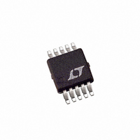
LTC4053EMSE-4.2#TR Linear Technology, LTC4053EMSE-4.2#TR Datasheet - Page 13

LTC4053EMSE-4.2#TR
Manufacturer Part Number
LTC4053EMSE-4.2#TR
Description
IC BATT CHARGR LI-ION REG 10MSOP
Manufacturer
Linear Technology
Type
Battery Chargerr
Datasheet
1.LTC4053EMSE-4.2PBF.pdf
(16 pages)
Specifications of LTC4053EMSE-4.2#TR
Function
Charge Management
Battery Type
Lithium-Ion (Li-Ion)
Voltage - Supply
4.25 V ~ 6.5 V
Operating Temperature
-40°C ~ 85°C
Mounting Type
Surface Mount
Package / Case
10-TFSOP, 10-MSOP (0.118", 3.00mm Width) Exposed Pad
Output Current
500mA
Output Voltage
4.2V
Operating Supply Voltage (min)
4.25V
Operating Supply Voltage (max)
6.5V
Operating Temp Range
-40C to 85C
Package Type
MSOP
Mounting
Surface Mount
Pin Count
10
Operating Temperature Classification
Industrial
Lead Free Status / RoHS Status
Contains lead / RoHS non-compliant
Lead Free Status / RoHS Status
Contains lead / RoHS non-compliant
Other names
LTC4053EMSE-4.2TR
Available stocks
Company
Part Number
Manufacturer
Quantity
Price
Part Number:
LTC4053EMSE-4.2#TRLTC4053EMSE-4.2#PBF
Manufacturer:
LINEAR/凌特
Quantity:
20 000
APPLICATIO S I FOR ATIO
Regardless of mode, the voltage at the PROG pin is
proportional to the current being delivered to the battery.
Power Dissipation
The conditions that cause the LTC4053 to reduce charge
current due to the thermal protection feedback can be
approximated by considering the power dissipated in the
IC. For high charge currents, the LTC4053 power dissipa-
tion is approximately:
where P
voltage, V
charge current. It is not necessary to perform any worst-
case power dissipation scenarios because the LTC4053
will automatically reduce the charge current to maintain
the die temperature at approximately 105°C. However, the
approximate ambient temperature at which the thermal
feedback begins to protect the IC is:
Example: Consider an LTC4053 operating from a 5V wall
adapter providing 1.2A to a 3.75V Li-Ion battery. The
ambient temperature above which the LTC4053 will begin
to reduce the 1.2A charge current is approximately:
The LTC4053 can be used above 45°C, but the charge
current will be reduced below 1.2A. The approximate
charge current at a given ambient temperature can be
approximated by:
Consider the above example with an ambient temperature
of 55°C. The charge current will be reduced to approxi-
mately:
P
T
T
T
T
I
I
BAT
BAT
A
A
A
A
D
= 105°C – P
= 105°C – (V
= 105°C – (5V – 3.75V) • 1.2A • 40°C/W
= 105°C – 1.5W • 40°C/W = 105°C – 60°C = 45°C
= (V
=
=
D
BAT
is the power dissipated, V
CC
(
(
V
5
CC
V
– V
105
is the battery voltage, and I
– .
105
–
3 75
BAT
V
°
D
C T
BAT
CC
°
θ
U
) • I
C
JA
–
V
– V
–
)• θ
)•
BAT
A
55
40
BAT
U
JA
°
°
C
) • I
C W
/
BAT
W
=
CC
• θ
50
is the input supply
JA
50
°
BAT
C A
°
C
/
is the battery
U
=
1
A
Furthermore, the voltage at the PROG pin will change
proportionally with the charge current as discussed in the
Programming Charge Current section.
It is important to remember that LTC4053 applications do
not need to be designed for worst-case thermal conditions
since the IC will automatically reduce power dissipation
when the junction temperature reaches approximately
105°C.
Board Layout Considerations
The ability to deliver maximum charge current under all
conditions require that the exposed metal pad on the
backside of the LTC4053 package be soldered to the PC
board ground. Correctly soldered to a 2500mm
sided 1oz. copper board the LTC4053 has a thermal
resistance of approximately 40°C/W. Failure to make
thermal contact between the exposed pad on the backside
of the package and the copper board will result in thermal
resistances far greater than 40°C/W. As an example, a
correctly soldered LTC4053 can deliver over 1250mA to a
battery from a 5V supply at room temperature. Without a
backside thermal connection, this number could drop to
less than 500mA.
V
Many types of capacitors can be used for input bypassing.
However, caution must be exercised when using multi-
layer ceramic capacitors. Because of the self resonant and
high Q characteristics of some types of ceramic capaci-
tors, high voltage transients can be generated under some
start-up conditions, such as connecting the charger input
to a hot power source. For more information refer to
Application Note 88.
Stability
The constant-voltage mode feedback loop is stable
without any compensation provided that a battery is
connected. However, a 1µF capacitor with a 1Ω series
resistor to GND is recommended at the BAT pin to keep
ripple voltage low when the battery is disconnected.
In the constant-current mode it is the PROG pin that is in
the feedback loop and not the battery. The constant-
current mode stability is affected by the impedance at the
CC
Bypass Capacitor
LTC4053-4.2
2
13
double-
4053fa


