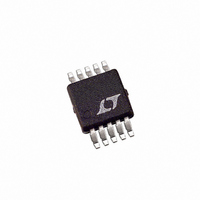
LTC4053EMSE-4.2#TR Linear Technology, LTC4053EMSE-4.2#TR Datasheet - Page 14

LTC4053EMSE-4.2#TR
Manufacturer Part Number
LTC4053EMSE-4.2#TR
Description
IC BATT CHARGR LI-ION REG 10MSOP
Manufacturer
Linear Technology
Type
Battery Chargerr
Datasheet
1.LTC4053EMSE-4.2PBF.pdf
(16 pages)
Specifications of LTC4053EMSE-4.2#TR
Function
Charge Management
Battery Type
Lithium-Ion (Li-Ion)
Voltage - Supply
4.25 V ~ 6.5 V
Operating Temperature
-40°C ~ 85°C
Mounting Type
Surface Mount
Package / Case
10-TFSOP, 10-MSOP (0.118", 3.00mm Width) Exposed Pad
Output Current
500mA
Output Voltage
4.2V
Operating Supply Voltage (min)
4.25V
Operating Supply Voltage (max)
6.5V
Operating Temp Range
-40C to 85C
Package Type
MSOP
Mounting
Surface Mount
Pin Count
10
Operating Temperature Classification
Industrial
Lead Free Status / RoHS Status
Contains lead / RoHS non-compliant
Lead Free Status / RoHS Status
Contains lead / RoHS non-compliant
Other names
LTC4053EMSE-4.2TR
Available stocks
Company
Part Number
Manufacturer
Quantity
Price
Part Number:
LTC4053EMSE-4.2#TRLTC4053EMSE-4.2#PBF
Manufacturer:
LINEAR/凌特
Quantity:
20 000
PACKAGE DESCRIPTIO
LTC4053-4.2
APPLICATIO S I FOR ATIO
PROG pin. With no additional capacitance on the PROG
pin, stability is acceptable with program resistor values as
high as 50k. However, additional capacitance on this node
reduces the maximum allowed program resistor. The pole
frequency at the PROG pin should be kept above 500kHz.
Therefore, if the PROG pin is loaded with a capacitance, C,
the following equation should be used to calculate the
maximum resistance value for R
3.50 ±0.05
14
NOTE:
1. DRAWING TO BE MADE A JEDEC PACKAGE OUTLINE M0-229 VARIATION OF (WEED-2).
2. DRAWING NOT TO SCALE
3. ALL DIMENSIONS ARE IN MILLIMETERS
R
CHECK THE LTC WEBSITE DATA SHEET FOR CURRENT STATUS OF VARIATION ASSIGNMENT
2.15 ±0.05
PROG
< 1/(6.283 • 5 × 10
RECOMMENDED SOLDER PAD PITCH AND DIMENSIONS
0.25 ± 0.05
1.65 ±0.05
(2 SIDES)
U
2.38 ±0.05
(2 SIDES)
U
5
0.50
BSC
• C)
Figure 5. Isolating Capacitive Load on PROG Pin and Filtering
PROG
W
0.675 ±0.05
U
:
PACKAGE
OUTLINE
LTC4053
GND
10-Lead Plastic DFN (3mm × 3mm)
PROG
5
(Reference LTC DWG # 05-08-1698)
U
(SEE NOTE 6)
TOP MARK
7
PIN 1
R
0.200 REF
PROG
DD Package
C
10k
FILTER
Average, rather than instantaneous, battery current may
be of interest to the user. For example, if a switching power
supply operating in low-current mode is connected in
parallel with the battery the average current being pulled
out of the BAT pin is typically of more interest than the
instantaneous current pulses. In such a case, a simple RC
filter can be used on the PROG pin to measure the average
battery current as shown in Figure 5. A 10k resistor is
added between the PROG pin and the filter capacitor and
monitoring circuit to ensure stability.
4. DIMENSIONS OF EXPOSED PAD ON BOTTOM OF PACKAGE DO NOT INCLUDE
5. EXPOSED PAD SHALL BE SOLDER PLATED
6. SHADED AREA IS ONLY A REFERENCE FOR PIN 1 LOCATION ON THE
MOLD FLASH. MOLD FLASH, IF PRESENT, SHALL NOT EXCEED 0.15mm ON ANY SIDE
TOP AND BOTTOM OF PACKAGE
4053 F05
CHARGE
CURRENT
MONITOR
CIRCUITRY
3.00 ±0.10
0.75 ±0.05
(4 SIDES)
0.00 – 0.05
1.65 ± 0.10
(2 SIDES)
BOTTOM VIEW—EXPOSED PAD
5
R = 0.115
6
2.38 ±0.10
(2 SIDES)
TYP
10
1
0.50 BSC
0.25 ± 0.05
0.38 ± 0.10
(DD10) DFN 1103
4053fa


