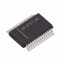
MAX1758EAI+ Maxim Integrated Products, MAX1758EAI+ Datasheet - Page 11

MAX1758EAI+
Manufacturer Part Number
MAX1758EAI+
Description
IC BATT CHRG 4-LI+ 28V SW 28SSOP
Manufacturer
Maxim Integrated Products
Datasheet
1.MAX1758EAI.pdf
(17 pages)
Specifications of MAX1758EAI+
Function
Charge Management
Battery Type
Lithium-Ion (Li-Ion)
Voltage - Supply
6 V ~ 28 V
Operating Temperature
-40°C ~ 85°C
Mounting Type
Surface Mount
Package / Case
28-SSOP
Output Voltage
5.4 V
Operating Supply Voltage
6 V to 28 V
Supply Current
5 mA
Maximum Operating Temperature
+ 85 C
Minimum Operating Temperature
- 40 C
Charge Safety Timers
Yes
Mounting Style
SMD/SMT
Temperature Monitoring
Yes
Lead Free Status / RoHS Status
Lead free / RoHS Compliant
The MAX1758 includes a state machine that controls
the charging algorithm. Figure 4 shows the state dia-
gram. Table 1 is the charging state table. When power
is applied, or SHDN input is driven high, the part goes
into the reset state where the timers are reset to zero to
prepare for charging. From the reset state, it enters the
prequalification state. In this state, 1/10 of the fast-
charge current charges the battery, and the battery
temperature and voltage are measured. If the voltage is
above the undervoltage threshold and the temperature
is within the limits, then it will enter the fast-charge
state. If the battery voltage does not rise above the
undervoltage threshold before the prequalification timer
expires, the charging terminates and the FAULT output
goes low. The prequalification time is set by the
TIMER1 capacitor (C
the temperature limits, charging and the timer are sus-
pended. Once the temperature is back within limits,
charging and the timer resume.
In the fast-charge state, the FASTCHG output goes low
and the batteries charge with a constant current (see
Charging Current Regulator section). If the battery volt-
age reaches the voltage limit before the fast timer
expires, the part enters the full-charge state. If the fast-
charge timer expires before the voltage limit is
reached, charging terminates and the FAULT output
goes low. The fast-charge time limit is set by the
TIMER2 capacitor (C
is outside the limits, charging pauses and the timers
are suspended until the temperature returns to within
the limits.
In the full-charge state, the FULLCHG output goes low
and the batteries charge at a constant voltage (see the
Voltage Regulation section). When the charging current
drops below 150mA (330mA peak inductor current), or
if the full-charge timer expires, the state machine enters
the top-off state. In the top-off state, the batteries con-
tinue to charge at a constant voltage until the top-off
timer expires when it enters the done state. In the done
state, charging stops until the battery voltage drops
below the recharge-voltage threshold when it enters the
reset state to start the charging process again. In the
full-charge or the top-off state, if the battery tempera-
ture is outside the limits, charging pauses and the
timers are suspended until the battery temperature
returns to within limits.
Li+ batteries require a high-accuracy voltage limit while
charging. The MAX1758 uses a high-accuracy voltage
regulator (±0.8%) to limit the charging voltage. The bat-
tery regulation voltage is nominally set to 4.2V per cell
and can be adjusted ±5% by changing the voltage at
Li+ Battery Charger with Internal 28V Switch
______________________________________________________________________________________
TIMER2
TIMER1
). If the battery temperature
). If the battery is outside
Voltage Regulator
Stand-Alone, Switch-Mode
the V
By limiting the adjust range of the regulation voltage, an
overall voltage accuracy of better than 1% is main-
tained while using 1% resistors. CELL sets the cell
count from 1-to-4 series cells (see Setting the Battery
Regulation Voltage section).
An internal error amplifier (GMV) maintains voltage reg-
ulation (Figure 3). The GMV amplifier is compensated
at CCV. The component values shown in Figure 1 pro-
vide suitable performance for most applications.
Individual compensation of the voltage regulation and
current regulation loops allows for optimum stability.
The charging current-limit regulator limits the charging
current. Current is sensed by measuring the voltage
across the internal current-sense resistor R
BATT and CS. The voltage at ISETOUT adjusts the
charging current. Full-scale charging current is
achieved when ISETOUT is connected to REF.
The charging current error amplifier (GMI) is compen-
sated at CCI. A 0.1µF capacitor at CCI provides suit-
able performance for most applications.
Figure 2. Charge State and Indicator Output Timing for a
Typical Charging Sequence
CURRENT
FASTCHG
FULLCHG
VOLTAGE
BATTERY
BATTERY
OUTPUT
OUTPUT
ADJ
OR SHDN HIGH
INSERTION
BATTERY
pin between reference voltage and ground.
(APPROX 85% CHARGE)
CHARGE
OPEN-
FAST-
STATE
DRAIN
LOW
VOLTAGE MODE
TRANSITION TO
Charging Current Regulator
CHARGE I = 1C
CHARGE
STATE
OPEN-
DRAIN
FULL-
LOW
(APPROX 95% CHARGE)
FULL-CHARGE TIMER
BATTERY CURRENT
DROPS TO C/10
TIMES OUT OR
TIMES OUT, END OF ALL
TOP-OFF
STATE
CHARGE FUNCTIONS
TOP-OFF TIMER
CS
between
DONE
11


