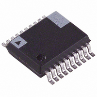
ADE7763ARS Analog Devices Inc, ADE7763ARS Datasheet - Page 15

ADE7763ARS
Manufacturer Part Number
ADE7763ARS
Description
IC ENERGY METER 1PHASE 20SSOP
Manufacturer
Analog Devices Inc
Specifications of ADE7763ARS
Input Impedance
390 KOhm
Measurement Error
0.1%
Voltage - I/o High
2.4V
Voltage - I/o Low
0.8V
Current - Supply
3mA
Voltage - Supply
4.75 V ~ 5.25 V
Operating Temperature
-40°C ~ 85°C
Mounting Type
Surface Mount
Package / Case
20-SSOP (0.200", 5.30mm Width)
Meter Type
Single Phase
For Use With
EVAL-ADE7763ZEB - BOARD EVALUATION FOR ADE7763
Lead Free Status / RoHS Status
Contains lead / RoHS non-compliant
Available stocks
Company
Part Number
Manufacturer
Quantity
Price
Part Number:
ADE7763ARS
Manufacturer:
ADI/亚德诺
Quantity:
20 000
Part Number:
ADE7763ARSZ
Manufacturer:
ADI/亚德诺
Quantity:
20 000
Part Number:
ADE7763ARSZRL
Manufacturer:
ADI/亚德诺
Quantity:
20 000
Note that the integrator has a –20 dB/dec attenuation and
approximately a –90° phase shift. When combined with a di/dt
sensor, the resulting magnitude and phase response should be a
flat gain over the frequency band of interest. The di/dt sensor
–89.70
–89.75
–89.80
–89.85
–89.90
–89.95
–90.00
–90.05
–90.10
–88.0
–88.5
–89.0
–89.5
–90.0
–90.5
–1.0
–1.5
–2.0
–2.5
–3.0
–3.5
–4.0
–4.5
–5.0
–5.5
–6.0
40
40
Digital Integrator and Phase Compensator (40 Hz to 70 Hz)
Digital Integrator and Phase Compensator (40 Hz to 70 Hz)
Figure 29. Combined Phase Response of the
Figure 31. Combined Phase Response of the
Digital Integrator and Phase Compensator
Figure 30. Combined Gain Response of the
45
45
10
2
50
50
FREQUENCY (Hz)
FREQUENCY (Hz)
FREQUENCY (Hz)
55
55
60
60
10
3
65
65
70
70
Rev. B | Page 15 of 56
has a 20 dB/dec gain. It also generates significant high
frequency noise, necessitating a more effective antialiasing filter
to avoid noise due to aliasing—see the Antialias Filter section.
When the digital integrator is switched off, the ADE7763 can be
used directly with a conventional current sensor such as a current
transformer (CT) or with a low resistance current shunt.
ZERO-CROSSING DETECTION
The ADE7763 has a zero-crossing detection circuit on Channel 2.
This zero crossing is used to produce an external zero-crossing
signal (ZX), which is used in the calibration mode (see the
Calibrating an Energy Meter section). This signal is also used to
initiate a temperature measurement (see the Temperature
Measurement section).
Figure 32 shows how the zero-crossing signal is generated from
the output of LPF1.
The ZX signal goes logic high upon a positive-going zero
crossing and logic low upon a negative-going zero crossing on
Channel 2. The ZX signal is generated from the output of LPF1.
LPF1 has a single pole at 140 Hz (@ CLKIN = 3.579545 MHz).
As a result, there is a phase lag between the analog input signal
V2 and the output of LPF1. The phase response of this filter is
shown in the Channel 2 Sampling section. The phase lag response
of LPF1 results in a time delay of approximately 1.14 ms
(@ 60 Hz) between the zero crossing on the analog inputs of
Channel 2 and the rising or falling edge of ZX.
Zero-crossing detection also drives the ZX flag in the interrupt
status register. The ZX flag is set to Logic 0 on the rising and
falling edge of the voltage waveform. It remains low until the
status register is read with reset. An active low in the IRQ output
appears if the corresponding bit in the interrupt enable register is
set to Logic 1.
The flag in the interrupt status register and the IRQ output are
set to their default values when reset (RSTSTATUS) is read in
the interrupt status register.
V2
V2P
V2N
0.93
1.0
PGA2
Figure 32. Zero-Crossing Detection on Channel 2
×
×
1,
8,
V2
{GAIN[7:5]}
×
×
2,
16
×
2.32° @ 60Hz
1,
REFERENCE
LPF1
f
ADC 2
–
3dB
LPF1
= 140Hz
ZX
1
–63% TO +63% FS
CROSSING
ZERO
ADE7763
TO
MULTIPLIER
ZX


