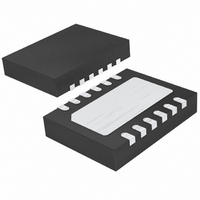
LTC4265IDE#PBF Linear Technology, LTC4265IDE#PBF Datasheet - Page 17

LTC4265IDE#PBF
Manufacturer Part Number
LTC4265IDE#PBF
Description
IC CTRLR PD INTERFACE HP 12-DFN
Manufacturer
Linear Technology
Type
Power over Ethernet Switch (PoE)r
Datasheet
1.LTC4265IDEPBF.pdf
(20 pages)
Specifications of LTC4265IDE#PBF
Applications
Remote Peripherals (Industrial Controls, Cameras, Data Access)
Internal Switch(s)
Yes
Operating Temperature
-40°C ~ 85°C
Mounting Type
Surface Mount
Package / Case
12-WFDFN Exposed Pad
Input Voltage
60V
Supply Current
1.35mA
Digital Ic Case Style
DFN
No. Of Pins
12
Uvlo
30V
Operating Temperature Range
-40°C To +85°C
Msl
MSL 1 - Unlimited
Termination Type
SMD
Rohs Compliant
Yes
Filter Terminals
SMD
Controller Type
Hot Swap
Lead Free Status / RoHS Status
Lead free / RoHS Compliant
Available stocks
Company
Part Number
Manufacturer
Quantity
Price
APPLICATIONS INFORMATION
IEEE 802.3at SYSTEM POWER-UP REQUIREMENT
Under the IEEE 802.3at standard, a PD must operate under
12.95 Watts in accordance with IEEE 802.3af standards
until it recognizes a Type-2 PSE. Initializing PD operation
in 12.95-Watt mode eliminates interoperability issue in
case a Type-2 PD is connects to a Type-1 PSE. Once the
PD recognizes a Type-2 PSE, the IEEE 802.3at standard
requires the PD to wait 80ms in 12.95W operation before
25.5W operation can commence.
MAINTAIN POWER SIGNATURE
In an IEEE 802.3af/at system, the PSE uses the maintain
power signature (MPS) to determine if a PD continues to
require power. The MPS requires the PD to periodically draw
at least 10mA and also have an AC impedance less than
26.25k in parallel with 0.05μF . If one of these conditions
is not met, the PSE may disconnect power to the PD.
LAYOUT CONSIDERATION FOR THE LTC4265
The LTC4265 is relatively immune to layout problems.
Here are some recommendations.
Avoid excessive parasitic capacitance on the R
and place resistor R
Connect the LTC4265 exposed pad to a PC board heat
sink. Make the heat sink as large as possible.
Place the input capacitor and transient voltage suppres-
sor (C14 and D3 in Figure 7) as close to the LTC4265 as
possible.
If using the SHDN pin for auxiliary power application,
separate the SHDN pin from other high voltage connec-
tions, like GND and V
coupling shutting down the LTC4265.
CLASS
OUT
, to avoid leakage and capacitive
close to the LTC4265.
LTC4265
CLASS
17
4265fa
pin


