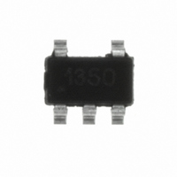
ZXLD1350ET5TA Diodes Zetex, ZXLD1350ET5TA Datasheet - Page 17

ZXLD1350ET5TA
Manufacturer Part Number
ZXLD1350ET5TA
Description
IC LED DRIVR WHITE BCKLGT TSOT-5
Manufacturer
Diodes Zetex
Type
Backlight, White LEDr
Specifications of ZXLD1350ET5TA
Topology
PWM, Step-Down (Buck)
Number Of Outputs
1
Internal Driver
Yes
Type - Primary
Automotive
Type - Secondary
High Brightness LED (HBLED), White LED
Frequency
1MHz
Voltage - Supply
7 V ~ 30 V
Voltage - Output
30V
Mounting Type
Surface Mount
Package / Case
TSOT-23-5, TSOT-5, TSOP-5
Operating Temperature
-40°C ~ 105°C
Current - Output / Channel
350mA
Internal Switch(s)
Yes
Efficiency
95%
Operating Supply Voltage (typ)
9/12/15/18/24V
Number Of Segments
3
Operating Temperature (min)
-40C
Operating Temperature (max)
105C
Operating Temperature Classification
Industrial
Package Type
TSOT-23
Pin Count
5
Mounting
Surface Mount
Power Dissipation
450mW
Operating Supply Voltage (min)
7V
Operating Supply Voltage (max)
30V
Lead Free Status / RoHS Status
Lead free / RoHS Compliant
Other names
ZXLD1350ET5TR
Available stocks
Company
Part Number
Manufacturer
Quantity
Price
Company:
Part Number:
ZXLD1350ET5TA
Manufacturer:
TI
Quantity:
4 300
Company:
Part Number:
ZXLD1350ET5TA
Manufacturer:
ZETEX
Quantity:
249 000
Part Number:
ZXLD1350ET5TA
Manufacturer:
DIODES/美台
Quantity:
20 000
ZXLD1350
Document number: DS33468 Rev. 8 - 2
Application Information (Continued)
Inductor Selection
Recommended inductor values for the ZXLD1350 are in the range 47µH to 220µH.
Higher values of inductance are recommended at higher supply voltages in order to minimize errors due to switching delays,
which result in increased ripple and lower efficiency. Higher values of inductance also result in a smaller change in output
current over the supply voltage range. (See graphs). The inductor should be mounted as close to the device as possible with
low resistance connections to the LX and V
The chosen coil should have a saturation current higher than the peak output current and a continuous
current rating above the required mean output current.
Suitable coils for use with the ZXLD1350 are listed in the table below:
The inductor value should be chosen to maintain operating duty cycle and switch 'on'/'off' times within the specified limits over
the supply voltage and load current range.
The following equations can be used as a guide, with reference to Figure 1 - Operating waveforms.
LX Switch 'On' time
Note: t
LX Switch 'Off' time
Note: t
Where:
t
t
ON
OFF
NP04SB470M
MSS6132ML
CD104-MC
DO1608C
Part No.
=
=
V
ONnmin
OFFmin
V
L is the coil inductance (H)
r
I
ΔI is the coil peak-peak ripple current (A) {Internally set to 0.3 x I
V
V
R
V
IN
avg
L
LED
IN
LED
LX
D
is the coil resistance (Ω)
−
is the rectifier diode forward voltage at the required load current (V)
is the supply voltage (V)
is the required LED current (A)
V
is the switch resistance (Ω)
+
is the total LED forward voltage (V)
LED
> 200ns
> 200ns
V
D
−
+
L
I
(µH)
avg
I
100
220
Δ
avg
47
47
68
47
L
L
I
Δ
×
×
I
(
R
(
R
S
S
DCR
+
0.64
0.55
0.27
0.38
0.58
0.82
+
(V)
r
r
L
L
+
)
R
LX
)
0.56
0.47
0.39
0.53
0.38
I
(A)
0.5
SAT
IN
pins.
Manufacturer
Taiyo Yuden
CoilCraft
www.diodes.com
Sumida
17 of 22
30V 350mA LED DRIVER with AEC-Q100
avg
}
Diodes Incorporated
A Product Line of
© Diodes Incorporated
ZXLD1350
March 2011


