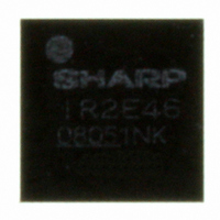
IR2E46Y6 Sharp Microelectronics, IR2E46Y6 Datasheet

IR2E46Y6
Specifications of IR2E46Y6
IR2E46Y7
Related parts for IR2E46Y6
IR2E46Y6 Summary of contents
Page 1
IR2E46Y ■Description IR2E46Y incorporates the illumination driver and the flash driver for an RGB-LED, and is equipped with the step-up DC/DC converter. This product is optimum for use as the RGB-LED driver IC for PDA and cellular phone applications, etc. ...
Page 2
R1:50kΩ C1:8pF VREF IREF RIREF IREF 6.8kΩ PGND OSC AGND CVIN VDD1 VDD2 SCL I2C Interface SDA ADD0 Register ADD1 R2 C2 39kΩ 220pF LEDGND R3 700kΩ R4 ERROR 50kΩ AMP VDAC UVLO DC/DC ...
Page 3
Dimensions (Note)It is those with an underline printing in a date code because of a LEAD-FREE type. INDEX(laser marking) A TOP VIEW S 0.1 SIDE VIEW 3.57±0. BOTTOM VIEW Package name : WLP033-X-3636 Lead ...
Page 4
Name Pin No Pin name A1 U1 Non-connect. This terminal is connected pin No. F1(U1). A2 ENG Enable input terminal for G. A3 ENB Enable input terminal for B. A4 LX1 SW Tr. drain terminal. A5 LX2 SW Tr. ...
Page 5
Assignment ENG B R VDD2 LEDGND ADD1 E STRIG SDA F U1 ADD0 Note: Pins are located on the underside ENB LX1 ENR PGND NC B XSTBY EI SCL IREF ...
Page 6
Maximum Ratings Parameter Power supply LX1,LX2,LX3,LX4 Terminal voltage Output current Power dissipation Derating ratio Operating temperature range Storage temperature range Note1: Free convection,on-board,compiled with SEMI42-996 ■Recommended Operating Condition Parameter Power supply LX1,LX2,LX3,LX4 Terminal voltage communication frequency ...
Page 7
Characteristics See the Block Diagram unless otherwise specified. VDD1=VDD2=3.6V, ENR=ENG=ENB=XSTBY=3.6V, ADD0=ADD1=STRIG=0V, R=G=B=1.0V, Ta=25° register setting: XSTB=1, BOOST=1 2 The current direction is regarded positive when entering the IC and negative when exiting. Current consumption Parameter Stand-by supply ...
Page 8
Constant current driver circuit Parameter R output current (stroboscopic mode) R output current (illumination mode) G output current (stroboscopic mode) G output current (illumination mode) B output current (stroboscopic mode) B output current (illumination mode) R terminal leak current G ...
Page 9
I 2 C-BUS Interface timing characteristics All specified output timings are based on 20% and 80% of VDD. Fs-mode Parameter SCL clock frequency Hold time(repeated) START condition LOW period of the SCL clock HIGH period of the SCL clock ...
Page 10
Fig.1 I C-Bus timing diagram (Fs-mode) SDA tf tLOW tr SCL tHD;STA tHD;DAT 2 Fig.2 I C-Bus timing diagram (Hs-mode) SDAH tSU;STA tHD;STA SCLH tfCL1 tSU;DAT tHD;STA tf tSU;STA tHIGH tHIGH tHD;DAT tSU;DAT trCL tLOW tLOW tfCL tHIGH IR2E46Y ...
Page 11
Example of typical characteristics Fig.3 fOSC vs. VDD VDD (V) VDD (V) Fig.5 IDD vs. VDD IDD vs. VDD VDD (V) VDD (V) Fig.4 fOSC vs. temperature Temperature ( Temperature ( Fig.6 IDD vs. temperature IDD vs. temperature Temperature ...
Page 12
Fig.7 IOUT(R) vs. Terminal voltage Fig.9 IOUT(G) vs. Terminal voltage Voltage and current pulse of pre illuminating (RGB each 20mA) to flashing (R=80mA, G=120mA, B=75mA). Pin: VDD1=VDD2=3.6V, ENR=ENG=ENB=XSTBY=3.6V, ADD0=ADD1=STRIG=0V Resister setting: RSLSET:h’F1, GBSLSET: h’01, STSET: h’10, RGSDSET:h’10, GBSDSET: h’3F, RIDSET: ...
Page 13
VDD2 pin) with the shortest distance and set terminals same potential. ・Connect the grounding terminals (PGND pin, SWGND pin, AGND pin, and LEDGND pin) with the shortest distance and set terminals ...
Page 14
Notices · The circuit application examples in this publication are provided to explain representative applications of SHARP devices and are not intended to guarantee any circuit design or license any intellectual property rights. SHARP takes no responsibility for any ...


