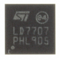
LED7707TR STMicroelectronics, LED7707TR Datasheet - Page 35

LED7707TR
Manufacturer Part Number
LED7707TR
Description
IC LED DRIVR WHT BCKLT 24-VFQFPN
Manufacturer
STMicroelectronics
Type
Backlight, White LEDr
Datasheet
1.LED7707TR.pdf
(47 pages)
Specifications of LED7707TR
Topology
PWM, Step-Up (Boost)
Number Of Outputs
6
Internal Driver
Yes
Type - Primary
Backlight
Type - Secondary
White LED
Frequency
250kHz ~ 1MHz
Voltage - Supply
4.5 V ~ 36 V
Voltage - Output
36V
Mounting Type
Surface Mount
Package / Case
24-VFQFN, 24-VFQFPN
Operating Temperature
0°C ~ 85°C
Current - Output / Channel
85mA
Internal Switch(s)
Yes
High Level Output Current
85 mA
Operating Supply Voltage
4.5 V to 36 V
Maximum Supply Current
1 mA
Maximum Power Dissipation
2.3 W
Maximum Operating Temperature
+ 150 C
Mounting Style
SMD/SMT
Minimum Operating Temperature
- 40 C
For Use With
497-10044 - BOARD EVAL LCD BACKLIGHT LED7707
Lead Free Status / RoHS Status
Lead free / RoHS Compliant
Efficiency
-
Lead Free Status / Rohs Status
Details
Other names
497-8492-2
Available stocks
Company
Part Number
Manufacturer
Quantity
Price
Company:
Part Number:
LED7707TR
Manufacturer:
ST
Quantity:
12 000
Company:
Part Number:
LED7707TR
Manufacturer:
STMicroelectronics
Quantity:
10 000
LED7707
6.4.6
6.4.7
6.4.8
Over-voltage protection divider setting
The over-voltage protection (OVP) divider provides a partition of the output voltage to the
OVSEL pin. The OVP divider setting not only fixes the OVP threshold, but also the open-
channel detection threshold.
The proper OVP divider setting can be calculated by the equation (3):
Equation 38
where V
the maximum V
Equation 39
R
the resistor divider. For example, setting R
standard commercial value is R
Compensation network
For the compensation network, the suggestions provided in
In this condition, tentatively the following value of R3 and C8 (see
good choice for the loop stability:
R3 = 2.4 kΩ
C8 = 4.7 nF
Boost current limit
The boost current limit is set to protect the internal power switch against excessive current.
The slope compensation may reduce the programmed current limit. Hence, to take into
account this effect, as a rule of thumb, the current limit can be set as twice as much the
maximum inductor peak current (see
I
Therefore, using equation (7) and choosing I
Equation 40
BOOST, PEAK
1
can be chosen is in the order of hundreds of kilo-ohms to reduce the leakage current in
OUT, MAX
> 3.83 A
F
is the maximum output voltage considering the worst case (all LEDs with
= V
F,max
V
OUT
= 3.7 V on the same row):
R
,
OVP
2
R
2
=
BILIM
= 22 kΩ.
=
R
nLED
1
⋅
Section 6.4.4
=
V
I
OUT
BOOST
⋅
1
V
,
MAX
= 510 kΩ leads to R
K
, F
BOOST, PEAK
max
B
,
PEAK
. 1
+
145
+
4
):
V
700
=
V
−
300
. 1
mV
145
= 4 A, R
k
Ω
=
Section 6.1
V
26
6 .
2
V
BILIM
= 21.89 kΩ. The closest
Figure 24
Application information
will be:
are always valid.
) are usually a
35/47


