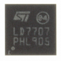
LED7707TR STMicroelectronics, LED7707TR Datasheet - Page 38

LED7707TR
Manufacturer Part Number
LED7707TR
Description
IC LED DRIVR WHT BCKLT 24-VFQFPN
Manufacturer
STMicroelectronics
Type
Backlight, White LEDr
Datasheet
1.LED7707TR.pdf
(47 pages)
Specifications of LED7707TR
Topology
PWM, Step-Up (Boost)
Number Of Outputs
6
Internal Driver
Yes
Type - Primary
Backlight
Type - Secondary
White LED
Frequency
250kHz ~ 1MHz
Voltage - Supply
4.5 V ~ 36 V
Voltage - Output
36V
Mounting Type
Surface Mount
Package / Case
24-VFQFN, 24-VFQFPN
Operating Temperature
0°C ~ 85°C
Current - Output / Channel
85mA
Internal Switch(s)
Yes
High Level Output Current
85 mA
Operating Supply Voltage
4.5 V to 36 V
Maximum Supply Current
1 mA
Maximum Power Dissipation
2.3 W
Maximum Operating Temperature
+ 150 C
Mounting Style
SMD/SMT
Minimum Operating Temperature
- 40 C
For Use With
497-10044 - BOARD EVAL LCD BACKLIGHT LED7707
Lead Free Status / RoHS Status
Lead free / RoHS Compliant
Efficiency
-
Lead Free Status / Rohs Status
Details
Other names
497-8492-2
Available stocks
Company
Part Number
Manufacturer
Quantity
Price
Company:
Part Number:
LED7707TR
Manufacturer:
ST
Quantity:
12 000
Company:
Part Number:
LED7707TR
Manufacturer:
STMicroelectronics
Quantity:
10 000
Application information
6.5
38/47
Layout consideration
1.
2.
3.
4.
5.
6.
7.
8.
9.
10. The capacitors of the compensated divider connected to the OVSEL pin should be
11. In order to assure good performance in terms of row current accuracy/mismatch, the
12. The capacitors of the filter connected to LDO5 and VIN pins should be mounted as
Figure 22
respectively).
A careful PCB layout is important for proper operation. In this section some guidelines
are provided in order to achieve a good layout.
The device has two different ground pins: signal ground (SGND) and power ground
(PGND). The PGND pin handles the switching current related to the boost section; for
this reason the PCB traces should be kept as short as possible and with adequate
width.
The signal ground is the return for the device supply and the current generators and
can be connected to the thermal pad.
The heat dissipation area (adequate to the application conditions) should be placed
backside respect to the device and with the lowest thermal impedance possible (i.e.
PCB traces in the backside should be avoided). The dissipation area is thermally and
electrically connected to the thermal pad by several vias (nine vias are recommended).
The signal and power grounds must be connected together in a single point as close as
possible to the PGND pin to reduce ground loops.
The R-C components of the compensation network should be placed as close as
possible to the COMP pin in order to avoid noise issue and instability of the
compensation.
Noise sensitive signals (i.e. feedbacks and compensation) should be routed as short as
possible to minimize noise collection. The LED7707 pinout makes it easy to separate
power components (e.g. inductor, diode) from signal ones.
The LX switching node should have and adequate width for high efficiency.
The critical power path inductor-LX-PGND must be as short as possible by mounting
the inductor, the diode and COUT as close as possible each other.
placed as close as possible to the OVSEL pin.
PCB traces from the rows pins to the LEDs should have similar length and width.
close as possible to the mentioned pins
and
Figure 23
shows the demonstration board layout (top view and bottom view
LED7707


