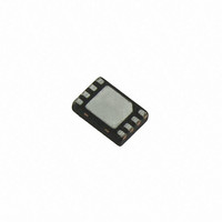
LDS8681008-T2 IXYS, LDS8681008-T2 Datasheet - Page 5

LDS8681008-T2
Manufacturer Part Number
LDS8681008-T2
Description
IC LED DRIVER PHOTO FLASH 16WQFN
Manufacturer
IXYS
Series
PowerLite™r
Type
Photo Flash LEDr
Datasheet
1.LDS8681008-T2.pdf
(9 pages)
Specifications of LDS8681008-T2
Topology
Linear (LDO), PWM, Switched Capacitor (Charge Pump)
Number Of Outputs
2
Internal Driver
Yes
Type - Primary
Flash/Torch
Type - Secondary
High Brightness LED (HBLED)
Voltage - Supply
2.7 V ~ 5.5 V
Mounting Type
Surface Mount
Package / Case
16-WQFN, 16-miniQFN
Current - Output / Channel
400mA
Internal Switch(s)
Yes
Efficiency
90%
Lead Free Status / RoHS Status
Lead free / RoHS Compliant
Voltage - Output
-
Frequency
-
Operating Temperature
-
Other names
LDS8681-002-T6
LDS8681-002-T6-2
LDS8681-002-T6-2
LDS8681008-T2-2
LDS8681-002-T6-2
LDS8681-002-T6-2
LDS8681008-T2-2
LDS8681
BLOCK DIAGRAM
BASIC OPERATION
LDS8681 is a charge pump designed for converting
at Li-Ion battery voltage to drive a white LED used in
photo flash applications. The LEDs current is factory
programmed at 400 mA for both channels. Consult
factory about other current values. Every LED may
be factory programmed separately in the range from
25 to 800 mA in 25 mA steps for LEDA and in the
range from 25 to 400 mA for LEDB.
The LDS8681 is in standby mode after applying V
voltage until logic HIGH level is applied to EN pin.
The device requires approximately 100 µs to wake
up.
Device starts operating with soft-start at 1-x mode to
minimize inrush current
At 1-x mode, the V
(less any internal voltage losses). If the output
voltage is sufficient to regulate all LED currents, the
device remains in 1-x operating mode.
The charge pump has two modes of operation: 1-X,
and 2-x. The device changes modes if the output
voltage drops below the minimum needed to support
the desired I
. The low dropout PowerLite™ Current regulator
(PCR) performs well at input voltages up to 150 mV
above LED forward voltage V
© 2009 IXYS Corp.
Characteristics subject to change without notice
LED
current.
OUT
is approximately equal to V
F
significantly increasing
Figure 2. LDS8681 Functional Block Diagram
IN
IN
5
driver’s efficiency. The LDS8681 monitors voltage
drop Vd across PCR at every channel in ON state. If
this voltage falls below 150 mV (typical) at any one
channel, (channel with LED with highest forward
voltage), the Mode Control Block changes charge
pump mode to the next multiplication ratio.
Vd (LEDA/B) = V
is a Charge Pump Output Resistance at given mode,
I
pump’ multiplication ratio.
If the input voltage is insufficient or falls to a level
where Vd ≤ 150 mV, and the regulated currents
cannot be maintained, the low dropout PowerLite™
Current Regulator switches the charge pump into 2-x
mode (after a fixed delay time of about 800μ s). In 2-x
mode,
approximately equal to 2 times the input supply
voltage (less any internal voltage losses).
LED Current Setting
The current in each of the two LED channels is
factory programmed; however, average current value
may be decreased using PWM pulses. Check LED
Data sheet to avoid LED thermal damage at high
current.
OUT
is sum of all LED currents, and M is a charge
the
charge
IN
x M – V
pump’
F
Doc. No. 8681_DS, Rev. N1.0
– Rcp x I
output
OUT
, where Rcp
voltage
is


