MAX7306AUB+ Maxim Integrated Products, MAX7306AUB+ Datasheet - Page 9
MAX7306AUB+
Manufacturer Part Number
MAX7306AUB+
Description
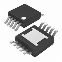
IC LED DRIVER LINEAR 10-UMAX
Manufacturer
Maxim Integrated Products
Type
Linear (I²C Interface)r
Datasheet
1.MAX7306AUB.pdf
(23 pages)
Specifications of MAX7306AUB+
Topology
PWM
Number Of Outputs
4
Internal Driver
Yes
Type - Primary
Backlight, LED Blinker
Type - Secondary
White LED
Frequency
1MHz
Voltage - Supply
1.62 V ~ 3.6 V
Mounting Type
Surface Mount
Package / Case
10-MSOP Exposed Pad, 10-HMSOP, 10-eMSOP
Operating Temperature
-40°C ~ 125°C
Current - Output / Channel
25mA
Internal Switch(s)
No
Lead Free Status / RoHS Status
Lead free / RoHS Compliant
Voltage - Output
-
Efficiency
-
Lead Free Status / Rohs Status
Details


Table 3. Configuration Register (0x26)
*Default state.
Table 4. Configuration Register (0x27)
*Default state.
SMBus/I
REGISTER BIT
REGISTER BIT
D4, D3, D2
D6, D5, D4
D7
D6
D5
D1
D0
D7
D3
D2
D1
D0
_______________________________________________________________________________________
Blink Prescaler Bits
Flag (Read-Only)
DESCRIPTION
Interrupt Status
Input Transition
DESCRIPTION
Transition Flag
2
P1/INT Output
P3/OSCOUT
(Read-Only)
Bus Timeout
RST Timer
P2/OSCIN
Reserved
RST POR
Reserved
C Interfaced 4-Port, Level-Translating
VALUE
VALUE
0/1
1*
1*
0*
0*
1*
1*
1*
1*
0
0
0
1
1
0
0
0
0
0
0
An interrupt has occurred on at least one interrupt enabled input port.
No interrupt has occurred on an interrupt enabled input port.
Transition has occurred on an input port.
No transition has occurred on an input port.
Reserved.
See Table 9 for blink frequency setting.
RST does not reset PWM/blink counters.
RST resets PWM/blink counters.
RST does not reset registers to power-on-reset state.
RST resets registers to power-on-reset state.
Enables the bus timeout feature.
Disables the bus timeout feature.
Reserved.
Sets P3 to output the oscillator.
Sets P3 as a GPIO controlled by register 0x03.
Sets P2 as the oscillator input.
Sets P2 as a GPIO controlled by register 0x02.
Sets P1 as the interrupt output.
Sets P1 as a GPIO controlled by register 0x01.
Set to 0 on power-up for proper transition detection.
GPIOs and LED Drivers
FUNCTION
FUNCTION
9
Related parts for MAX7306AUB+
Image
Part Number
Description
Manufacturer
Datasheet
Request
R

Part Number:
Description:
MAX7528KCWPMaxim Integrated Products [CMOS Dual 8-Bit Buffered Multiplying DACs]
Manufacturer:
Maxim Integrated Products
Datasheet:
Part Number:
Description:
Single +5V, fully integrated, 1.25Gbps laser diode driver.
Manufacturer:
Maxim Integrated Products
Datasheet:
Part Number:
Description:
Single +5V, fully integrated, 155Mbps laser diode driver.
Manufacturer:
Maxim Integrated Products
Datasheet:
Part Number:
Description:
VRD11/VRD10, K8 Rev F 2/3/4-Phase PWM Controllers with Integrated Dual MOSFET Drivers
Manufacturer:
Maxim Integrated Products
Datasheet:
Part Number:
Description:
Highly Integrated Level 2 SMBus Battery Chargers
Manufacturer:
Maxim Integrated Products
Datasheet:
Part Number:
Description:
Current Monitor and Accumulator with Integrated Sense Resistor; ; Temperature Range: -40°C to +85°C
Manufacturer:
Maxim Integrated Products
Part Number:
Description:
TSSOP 14/A�/RS-485 Transceivers with Integrated 100O/120O Termination Resis
Manufacturer:
Maxim Integrated Products
Part Number:
Description:
TSSOP 14/A�/RS-485 Transceivers with Integrated 100O/120O Termination Resis
Manufacturer:
Maxim Integrated Products
Part Number:
Description:
QFN 16/A�/AC-DC and DC-DC Peak-Current-Mode Converters with Integrated Step
Manufacturer:
Maxim Integrated Products
Part Number:
Description:
TDFN/A/65V, 1A, 600KHZ, SYNCHRONOUS STEP-DOWN REGULATOR WITH INTEGRATED SWI
Manufacturer:
Maxim Integrated Products
Part Number:
Description:
Integrated Temperature Controller f
Manufacturer:
Maxim Integrated Products
Part Number:
Description:
SOT23-6/I�/45MHz to 650MHz, Integrated IF VCOs with Differential Output
Manufacturer:
Maxim Integrated Products
Part Number:
Description:
SOT23-6/I�/45MHz to 650MHz, Integrated IF VCOs with Differential Output
Manufacturer:
Maxim Integrated Products
Part Number:
Description:
EVALUATION KIT/2.4GHZ TO 2.5GHZ 802.11G/B RF TRANSCEIVER WITH INTEGRATED PA
Manufacturer:
Maxim Integrated Products
Part Number:
Description:
QFN/E/DUAL PCIE/SATA HIGH SPEED SWITCH WITH INTEGRATED BIAS RESISTOR
Manufacturer:
Maxim Integrated Products
Datasheet: