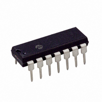
TC4467CPD Microchip Technology, TC4467CPD Datasheet - Page 10

TC4467CPD
Manufacturer Part Number
TC4467CPD
Description
IC MOSFET DVR QUAD NAND 14DIP
Manufacturer
Microchip Technology
Type
Microcontrollerr
Datasheet
1.TC4469CPD.pdf
(22 pages)
Specifications of TC4467CPD
Number Of Outputs
4
Package / Case
14-DIP (0.300", 7.62mm)
Configuration
Low-Side
Input Type
NAND
Delay Time
40ns
Current - Peak
1.2A
Number Of Configurations
4
Voltage - Supply
4.5 V ~ 18 V
Operating Temperature
0°C ~ 70°C
Mounting Type
Through Hole
Rise Time
25 ns
Fall Time
25 ns
Supply Voltage (min)
4.5 V
Supply Current
4 mA
Maximum Power Dissipation
800 mW
Maximum Operating Temperature
+ 70 C
Mounting Style
Through Hole
Minimum Operating Temperature
0 C
Number Of Drivers
4
Lead Free Status / RoHS Status
Lead free / RoHS Compliant
High Side Voltage - Max (bootstrap)
-
Lead Free Status / Rohs Status
Lead free / RoHS Compliant
Other names
158-1118
158-1118
158-1118
Available stocks
Company
Part Number
Manufacturer
Quantity
Price
Company:
Part Number:
TC4467CPD
Manufacturer:
Microchip Technology
Quantity:
135
Company:
Part Number:
TC4467CPD
Manufacturer:
UMC
Quantity:
6 220
TC4467/TC4468/TC4469
A
referenced loads is a function of duty cycle, load
current and output voltage. The power dissipation is
EQUATION
Quiescent power dissipation depends on input signal
duty cycle. Logic HIGH outputs result in a lower power
dissipation mode, with only 0.6 mA total current drain
(all devices driven). Logic LOW outputs raise the
current to 4 mA maximum. The quiescent power
dissipation is:
EQUATION
Transition power dissipation arises in the complimen-
tary configuration (TC446X) because the output stage
N-channel and P-channel MOS transistors are ON
simultaneously for a very short period when the output
changes.
approximately:
FIGURE 4-1:
DS21425B-page 10
1 µF Film
resistive-load-caused
1A
1B
2A
2B
3A
3B
4A
4B
D
V
I
I
I
D
V
L
H
L
O
S
=
=
=
=
=
=
=
1
2
3
4
5
6
8
9
Duty Cycle
Load Current
Duty Cycle
Quiescent Current with all outputs HIGH
(0.6 mA max.)
Quiescent Current with all outputs LOW
(4 mA max.)
Supply Voltage
Device Output Voltage
P
The
Q
=
V
V
transition
7
P
S
DD
14
L
D I
Switching Time Test Circuit.
=
H
DV
+
0.1 µF Ceramic
dissipation
O
13
12
11
10
I
1 D
power
L
–
I
L
dissipation
V
470 pF
OUT
for
supply-
Output
is
Input
(A, B)
V
+5 V
0V
DD
0 V
10%
EQUATION
Package power dissipation is the sum of load,
quiescent and transition power dissipations. An
example shows the relative magnitude for each term:
Maximum operating temperature is:
EQUATION
Note:
P
T
C
V
D
f
JA
J
D
S
=
t
=
=
D1
=
Input: 100 kHz,
square wave,
t
=
=
=
=
=
RISE
200 kHz
=
(83.3 C/W) 14-pin plastic package
1000 pF Capacitive Load
50%
Maximum allowable junction temperature
(+150 C
Ambient operating temperature should not
exceed +85°C for "EJD" device or +125°C
for "MJD" device.
15 V
Package Power Dissipation
P
45mW
110mW
90%
Junction-to-ambient thernal resistance
L
= t
+
T
10%
P
J
P
FALL
T
–
Q
+
=
+
35mW
JA
P
fV
T
t
P
10 nsec
R
s
D
10
2002 Microchip Technology Inc.
+
=
30mW
10
141 C
–
t
90%
D2
9
10%
90%
t
F


