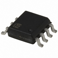
MIC5021YM Micrel Inc, MIC5021YM Datasheet - Page 6

MIC5021YM
Manufacturer Part Number
MIC5021YM
Description
IC DRIVER MOSF HI SIDE HS 8-SOIC
Manufacturer
Micrel Inc
Datasheet
1.MIC5021YM_TR.pdf
(10 pages)
Specifications of MIC5021YM
Configuration
High-Side
Input Type
Non-Inverting
Delay Time
500ns
Number Of Configurations
1
Number Of Outputs
1
Voltage - Supply
12 V ~ 36 V
Operating Temperature
-40°C ~ 85°C
Mounting Type
Surface Mount
Package / Case
8-SOIC (3.9mm Width)
Device Type
High Side
Module Configuration
High Side
Input Delay
500ns
Output Delay
800ns
Supply Voltage Range
12V To 36V
Driver Case Style
SOIC
No. Of Pins
8
Number Of Drivers
1
Driver Configuration
Non-Inverting
Driver Type
High Side
Input Logic Level
TTL
Rise Time
500ns
Fall Time
500ns
Frequency (max)
150MHz
Operating Supply Voltage (max)
36V
Operating Supply Voltage (min)
12V
Turn Off Delay Time
1.5ps
Turn On Delay Time (max)
1ns
Operating Temp Range
-40C to 85C
Operating Temperature Classification
Industrial
Mounting
Surface Mount
Pin Count
8
Lead Free Status / RoHS Status
Lead free / RoHS Compliant
Current - Peak
-
High Side Voltage - Max (bootstrap)
-
Lead Free Status / RoHS Status
Compliant, Lead free / RoHS Compliant
Other names
576-2354
MIC5021YM
MIC5021YM
Available stocks
Company
Part Number
Manufacturer
Quantity
Price
Company:
Part Number:
MIC5021YM
Manufacturer:
ROHM
Quantity:
7 167
Part Number:
MIC5021YM
Manufacturer:
MICREL/麦瑞
Quantity:
20 000
MIC5021
Logic-Level MOSFET Precautions
Logic-level MOSFETs have lower maximum gate-to-source
voltage ratings (typically ±10V) than standard MOSFETs
(typically ±20V). When an external MOSFET is turned on,
the doubling effect of the boost capacitor can cause the
gate-to-source voltage to momentarily exceed 10V. Internal
zener diodes clamp this voltage to 16V maximum which
is too high for logic-level MOSFETs. To protect logic-level
MOSFETs, connect a zener diode (5V≤V
gate to source.
Overcurrent Limiting
A 50mV comparator is provided for current sensing. The low
level trip point minimizes I
is used for current sensing.
The adjustable retry feature can be used to handle loads with
high initial currents, such as lamps or heating elements, and
can be adjusted from the C
C
overcurrent condition.
C
The default duty cycle (C
to the electrical characteristics when selecting a capacitor for
reduced duty cycle.
C
Increasing the duty cycle increases the power dissipation
in the load and MOSFET under a “fault” condition. Circuits
may become unstable at a duty cycle of about 75% or higher,
depending on conditions. Caution: The MIC5021 may be
damaged if the voltage applied to C
maximum voltage rating.
Boost Capacitor Selection
The boost capacitor value will vary depending on the supply
voltage range.
MIC5021
T
T
T
through a pull-up resistor to V
open, or a capacitor to ground, causes automatic retry.
to ground maintains gate drive shutdown following an
10µF
TTL Input
Figure 1. 12V to 20V Configuration
1
2
3
4
V
Input
C
Gnd
DD
T
MIC5021
T
open) is approximately 20%. Refer
2
V
Sense-
Sense+
T
R losses when a power resistor
B O O S T
Gate
connection.
DD
8
7
6
5
increases the duty cycle.
T
exceeds the absolute
+12V to +20V
0.01
µF
Zener
Load
<10V) from
6
A 0.01µF boost capacitor is recommended for best perfor-
mance in the 12V to 20V range. Refer to figure 1. Larger
capacitors may damage the MIC5021.
If the full 12V to 36V voltage range is required, the boost
capacitor value must be reduced to 2.7nF. Refer to Figure
2. The recommended configuration for the 20V to 36V range
is to place the capacitor is placed between V
as shown in Figure 3.
Do not use both boost capacitor between V
MOSFET source and V
Current Sense Resistors
Lead length can be significant when using low value (< 1Ω)
resistors for current sensing. Errors caused by lead length
can be avoided by using four-teminal current sensing re-
sistors. Four-terminal resistors are available from several
manufacturers.
Figure 3. Preferred 20V to 36V Configuration
10µF
TTL Input
10µF
TTL Input
Figure 2. 12V to 36V Configuration
1
2
3
4
1
2
3
4
V
Input
C
Gnd
V
Input
C
Gnd
DD
T
DD
T
MIC5021
MIC5021
BOOST
V
Sense-
Sense+
V
Sense-
Sense+
B O O S T
Gate
BOOST
Gate
and V
8
7
6
5
8
7
6
5
DD
+12V to +36V
+12V to +36V
2.7
nF
0.01
µF
at the same time.
DD
BOOST
Load
Load
and V
Micrel, Inc.
July 2005
and the
BOOST


