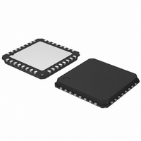
AMIS30624C6245RG ON Semiconductor, AMIS30624C6245RG Datasheet - Page 32

AMIS30624C6245RG
Manufacturer Part Number
AMIS30624C6245RG
Description
IC STEPPER DVR I2C 800MA 32-NQFP
Manufacturer
ON Semiconductor
Type
I2C Micro Stepping Motor Driverr
Datasheet
1.AMIS30624C6244RG.pdf
(56 pages)
Specifications of AMIS30624C6245RG
Applications
Stepper Motor Driver, 2 Phase
Number Of Outputs
1
Current - Output
800mA
Voltage - Supply
8 V ~ 29 V
Operating Temperature
-40°C ~ 165°C
Mounting Type
Surface Mount
Package / Case
32-VSQFP
Product
Stepper Motor Controllers / Drivers
Operating Supply Voltage
8 V to 29 V
Supply Current
800 mA
Mounting Style
SMD/SMT
Lead Free Status / RoHS Status
Lead free / RoHS Compliant
Voltage - Load
-
Lead Free Status / Rohs Status
Lead free / RoHS Compliant
Other names
766-1002-2
Available stocks
Company
Part Number
Manufacturer
Quantity
Price
Company:
Part Number:
AMIS30624C6245RG
Manufacturer:
ON Semiconductor
Quantity:
212
Company:
Part Number:
AMIS30624C6245RG
Manufacturer:
ON Semiconductor
Quantity:
1 850
Company:
Part Number:
AMIS30624C6245RG
Manufacturer:
ON Semiconductor
Quantity:
10 000
AMIS-30624
zoom over one micro-step in Figure 19 shows how the PWM circuit performs this regulation. To reduce the current ripple, a higher
PWM frequency should be selectable. The RAM register PWMfreq is used for this (Bit 6 in Data 7 of
Table 21: PWM Frequency Selection
14.3.3. PWM Jitter
To lower the power spectrum for the fundamental and higher harmonics of the PWM frequency, jitter can be added to the PWM clock.
The RAM register PWMJEn is used for this. (Bit 0 in Data 7 of
Readout with GetFullStatus1.
Table 22: PWM Jitter Selection
14.3.4. Motor Starting Phase
At motion start, the currents in the coils are directly switched from Ihold to Irun with a new sine/cosine ratio corresponding to the first
half (or micro) step of the motion.
14.3.5. Motor Stopping Phase
At the end of the deceleration phase, the currents are maintained in the coils at their actual DC level (hence keeping the sine/cosine
ratio between coils) during the stabilization time t
sin(TagPos) and Ihold x cos(TagPos) as illustrated below. A new positioning order can then be executed.
14.3.6. Charge Pump Monitoring
If the charge pump voltage is not sufficient for driving the high side transistors (due to a failure), an internal
issued. This is acknowledged to the master by raising the flag <CPFail> (available with command GetFullStatus1).
In case this failure occurs while a motion is ongoing, the flag <StepLoss> is also raised.
PWMfreq
PWMJEn
0
1
0
1
stab
Rev. 4 | Page 32 of 56 | www.onsemi.com
(see Table 6). The currents are then set to the hold values, respectively, Ihold x
Figure 20: Motor Stopping Phase
SetMotorParam
Added jitter to PWM frequency
Applied PWM Frequency
Single PWM frequency
or
SetStallParam).
22.8 kHz
45.6 kHz
Status
SetMotorParam
HardStop
).
command is


