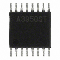
A3950SLPTR-T Allegro Microsystems Inc, A3950SLPTR-T Datasheet

A3950SLPTR-T
Specifications of A3950SLPTR-T
A3950SLPTR-T
Available stocks
Related parts for A3950SLPTR-T
A3950SLPTR-T Summary of contents
Page 1
Features and Benefits ▪ Low R outputs DS(on) ▪ Overcurrent protection ▪ Motor lead short-to-supply protection ▪ Short-to-ground protection ▪ Sleep function ▪ Synchronous rectification ▪ Diagnostic output ▪ Internal undervoltage lockout (UVLO) ▪ Crossover-current protection Packages: Package LP, 16 ...
Page 2
... A3950 Selection Guide Part Number A3950SLPTR-T 13 in. reel, 4000 pieces / reel A3950SEUTR-T 7 in. reel, 1500 pieces / reel Absolute Maximum Ratings Characteristic Load Supply Voltage Output Current Sense Voltage VBB to OUTx OUTx to SENSE Logic Input Voltage Operating Ambient Temperature Maximum Junction Temperature ...
Page 3
A3950 VREG 0.22 μ MODE PHASE V DD ENABLE 5 kΩ SLEEP 5 kΩ NFAULT Terminal List Table Name EU NFAULT 15 MODE 16 PHASE 1 GND 2, 12 SLEEP 3 ENABLE 4 OUTA 6 SENSE 7 VBB ...
Page 4
A3950 ELECTRICAL CHARACTERISTICS 25°C, V Characteristics Motor Supply Current PHASE, ENABLE, MODE Input Voltage SLEEP Input Voltage PHASE, MODE Input Current 1 ENABLE Input Current SLEEP Input Current NFAULT Output Voltage Input Hysteresis, except SLEEP Output ...
Page 5
A3950 SLEEP ENABLE PHASE MODE OUTA OUTB 0 I OUTX OutA 3 A Charge pump and VREG power-on delay (≈200 μs) DMOS Full-Bridge Motor Driver Timing Diagram: PWM Control ...
Page 6
A3950 V OUTA High-Z V OUTB I PEAK I OCP I OUTx ENABLE, Source or Sink BLANK Charge Pump Counter NFAULT Motor lead short condition DMOS Full-Bridge Motor Driver Timing Diagram: Overcurrent Control t t BLANK OCP Normal dc motor ...
Page 7
A3950 Device Operation. The A3950 is designed to operate one DC motor. The output drivers are all low R drivers that feature internal synchronous rectification to reduce power dissipation. PHASE and ENABLE inputs allow two-wire control with an additional MODE ...
Page 8
A3950 NFAULT low, but does not disable the operation of the chip. If the die temperature increases further, to approximately 175°C, the full-bridge outputs will be disabled until the internal temperature falls below a hysteresis of 15°C. Overcurrent Protection. Referring ...
Page 9
A3950 Power Dissipation. First order approximation of power dissipation in the A3950 can be calculated by first examining the power dissipation in the full-bridge during each of the operation modes. The A3950 features synchronous rectifica- tion, a feature that effectively ...
Page 10
A3950 SENSE Pin. A low value resistor can be placed between the SENSE pin and ground for current sensing purposes. To mini- mize ground-trace IR drops in sensing the output current level, the current sensing resistor should have an independent ...
Page 11
A3950 4.00 ±0. 17X 0.08 C 0.30 ±0.05 0.65 0.40 ±0. 2.15 DMOS Full-Bridge Motor Driver EU Package, 16 Pin QFN with Exposed Thermal Pad 4.00 ±0.15 C SEATING PLANE 0.75 ...
Page 12
A3950 LP Package, 16 Pin TSSOP with Exposed Thermal Pad 5.00 ±0. 3.00 16X 0.10 C +0.05 0.65 0.25 –0.06 Copyright ©2005-2008, Allegro MicroSystems, Inc. The products described here are manufactured under one or more ...


