BA6238A Rohm Semiconductor, BA6238A Datasheet - Page 10
BA6238A
Manufacturer Part Number
BA6238A
Description
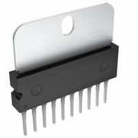
IC DRIVER REV MOTOR 2CH HSIP10
Manufacturer
Rohm Semiconductor
Specifications of BA6238A
Applications
DC Motor Driver
Number Of Outputs
2
Current - Output
1.6A
Voltage - Supply
8 V ~ 18 V
Operating Temperature
-25°C ~ 75°C
Mounting Type
Through Hole
Package / Case
10-SIP + Tab
Lead Free Status / RoHS Status
Lead free / RoHS Compliant
Voltage - Load
-
Available stocks
Company
Part Number
Manufacturer
Quantity
Price

Part Number:
BA6238A
Manufacturer:
ROHM/罗姆
Quantity:
20 000
Company:
Part Number:
BA6238AN
Manufacturer:
AD
Quantity:
9 654


External application components
Functional descriptions
○
BA6246, BA6246N, BA6247FP-Y, BA6239A, BA6238A, BA6238AN
c
www.rohm.com
2009 ROHM Co., Ltd. All rights reserved.
1) Resistor for the current limitation, R1
2) Resistors and zener diode for the output high voltage setting, R2, R3 and ZD
3) Stabilization capacitor for the power supply line, C1
4) Phase compensating capacitor, C2, C3, C4, C5
1) Operation modes
This is a current limiting resistor for collector loss reduction and at the time of short-circuited output. It depends on the
power supply voltage used, etc., but choose resistance of about 5 to 10Ω. In addition, set resistance with utmost care
to voltage drop caused by inrush current that flows when the motor is started.
These are the resistors and zener diode used when output high voltage is set. Zener diode ZD is recommended to be
used instead of resistor R3 when the power supply voltage is unstable for BA6246/N, BA6247FP-Y and BA6238A/AN.
Please connect the capacitor of 1μF to 100μF for the stabilization of the power supply line, and confirm the motor
operation.
Noise is generated in output pins or oscillation results in accord with the set mounting state such as power supply
circuit, motor characteristics, PCB pattern artwork, etc. As noise oscillation measures, connect 0.01μF to 0.1μF
capacitors.
* OPEN is the off state of all output transistors. Please note that this is the state of the connected diodes, which differs from that of the mechanical relay.
* OPEN is the off state of all output transistors. Please note that this is the state of the connected diodes, which differs from that of the mechanical relay.
IN1
IN1
H
H
H
H
L
L
L
L
IN2
IN2
H
H
H
H
L
L
L
L
Table 6 Logic table, BA6247FP-Y / BA6239A / BA6238A / BA6238AN
IN3
IN3
H
H
H
H
H
H
H
H
L
L
L
L
L
L
L
L
OPEN*
OUT1
OUT1
H
H
H
H
L
L
L
L
L
L
L
Table 5 Logic table, BA6246 / BA6246N
OPEN*
OPEN*
OPEN*
OPEN*
OPEN*
OUT2
OUT2
H
H
L
L
L
L
L
OPEN*
OPEN*
OPEN*
OPEN*
OPEN*
10/15
OUT3
OUT3
H
H
L
L
L
L
L
Motor 1, forward (OUT1 > OUT2)
Motor 1, reverse (OUT2 > OUT1)
Motor 2, forward (OUT1 > OUT3)
Motor 2, reverse (OUT3 > OUT1)
Motor 1, forward (OUT1 > OUT2)
Motor 1, reverse (OUT2 > OUT1)
Motor 2, forward (OUT1 > OUT3)
Motor 2, reverse (OUT3 > OUT1)
OPERATION
OPERATION
Brake (stop)
Brake (stop)
Brake (stop)
Stop (idling)
Technical Note
2009.04 - Rev.A
Related parts for BA6238A
Image
Part Number
Description
Manufacturer
Datasheet
Request
R

Part Number:
Description:
Manufacturer:
Rohm Semiconductor
Datasheet:
Part Number:
Description:
Manufacturer:
Rohm Semiconductor
Datasheet:
Part Number:
Description:
Manufacturer:
Rohm Semiconductor
Datasheet:
Part Number:
Description:
Manufacturer:
Rohm Semiconductor
Datasheet:
Part Number:
Description:
Manufacturer:
Rohm Semiconductor
Datasheet:
Part Number:
Description:
Manufacturer:
Rohm Semiconductor
Datasheet:
Part Number:
Description:
Manufacturer:
Rohm Semiconductor
Datasheet:
Part Number:
Description:
Manufacturer:
Rohm Semiconductor
Datasheet:
Part Number:
Description:
Manufacturer:
Rohm Semiconductor
Datasheet:
Part Number:
Description:
Manufacturer:
Rohm Semiconductor
Datasheet:
Part Number:
Description:
Manufacturer:
Rohm Semiconductor
Datasheet:
Part Number:
Description:
Manufacturer:
Rohm Semiconductor
Datasheet:

Part Number:
Description:
DIODE SWITCH 80V 25MA SMD5 TR
Manufacturer:
Rohm Semiconductor
Datasheet: