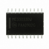
MC33033DWG ON Semiconductor, MC33033DWG Datasheet - Page 19

MC33033DWG
Manufacturer Part Number
MC33033DWG
Description
IC CTLR DC MOTOR BRSHLSS 20SOIC
Manufacturer
ON Semiconductor
Type
Brushless DC Motor Controllerr
Datasheet
1.MC33033DWR2G.pdf
(27 pages)
Specifications of MC33033DWG
Applications
DC Motor Controller, Brushless (BLDC), 3 Phase
Number Of Outputs
1
Current - Output
100mA
Voltage - Load
5.9 V ~ 6.5 V
Voltage - Supply
10 V ~ 30 V
Operating Temperature
-40°C ~ 85°C
Mounting Type
Surface Mount
Package / Case
20-SOIC (7.5mm Width)
Operating Supply Voltage
10 V to 30 V
Supply Current
22 mA
Mounting Style
SMD/SMT
Lead Free Status / RoHS Status
Lead free / RoHS Compliant
Other names
MC33033DWG
MC33033DWGOS
MC33033DWGOS
Available stocks
Company
Part Number
Manufacturer
Quantity
Price
Company:
Part Number:
MC33033DWG
Manufacturer:
ON
Quantity:
1 156
Company:
Part Number:
MC33033DWG
Manufacturer:
ON Semiconductor
Quantity:
284
Part Number:
MC33033DWG
Manufacturer:
ON/安森美
Quantity:
20 000
Three Phase Closed Loop Controller
speed control. For closed loop speed control, the MC33033
requires an input voltage proportional to the motor speed.
Traditionally this has been accomplished by means of a
tachometer to generate the motor speed feedback voltage.
Figure 38 shows an application whereby an MC33039,
powered from the 6.25 V reference (Pin 7) of the MC33033,
is used to generate the required feedback voltage without the
need of a costly tachometer. The same Hall sensor signals
used by the MC33033 for rotor position decoding are
utilized by the MC33039. Every positive or negative going
transition of the Hall sensor signals on any of the sensor lines
causes the MC33039 to produce an output pulse of defined
amplitude and time duration, as determined by the external
resistor R
The MC33033, by itself, is capable of open loop motor
10 k
0.01
Speed
Faster
100 k
1
and capacitor C
F/R
Figure 38. Closed Loop Brushless DC Motor Control With the MC33033 Using the MC33039
5.1 k
10
4
1
2
3
5
9
4
6
7
8
1
2
3
MC33033
Close Loop
MC33039
1.0 M
1
0.1
. The resulting output train of
14
13
12
20
19
18
17
16
15
11
6
1.0 k
1.0 k
8
5
7
4.7 k
J
1
TP1
1.0 M
R
750 pF
C
1
1
MC33033, NCV33033
Enable
1.1 k
1.0 k
http://onsemi.com
1N5819
1N4742
1.1 k
19
330
pulses present at Pin 5 of the MC33039 are integrated by the
Error Amplifier of the MC33033 configured as an
integrator, to produce a dc voltage level which is
proportional to the motor speed. This speed proportional
voltage establishes the PWM reference level at Pin 11 of the
MC33033 motor controller and completes or closes the
feedback loop. The MC33033 outputs drive a TMOS power
MOSFET 3-phase bridge. High current can be expected
during conditions of start-up and when changing direction
of the motor.
having 120/240 degrees Hall sensor electrical phasing. The
system can easily be modified to accommodate 60/300
degree Hall sensor electrical phasing by removing the
jumper (J
470
470
470
The system shown in Figure 38 is designed for a motor
V
M
0.1
1.1 k
(18 to 30 V)
1
0.1
) at Pin 18 of the MC33033.
0.1
33
100
1000
0.05/1.0 W
TP2
S
Motor
N
N
S


