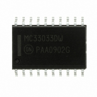
MC33033DWG ON Semiconductor, MC33033DWG Datasheet - Page 24

MC33033DWG
Manufacturer Part Number
MC33033DWG
Description
IC CTLR DC MOTOR BRSHLSS 20SOIC
Manufacturer
ON Semiconductor
Type
Brushless DC Motor Controllerr
Datasheet
1.MC33033DWR2G.pdf
(27 pages)
Specifications of MC33033DWG
Applications
DC Motor Controller, Brushless (BLDC), 3 Phase
Number Of Outputs
1
Current - Output
100mA
Voltage - Load
5.9 V ~ 6.5 V
Voltage - Supply
10 V ~ 30 V
Operating Temperature
-40°C ~ 85°C
Mounting Type
Surface Mount
Package / Case
20-SOIC (7.5mm Width)
Operating Supply Voltage
10 V to 30 V
Supply Current
22 mA
Mounting Style
SMD/SMT
Lead Free Status / RoHS Status
Lead free / RoHS Compliant
Other names
MC33033DWG
MC33033DWGOS
MC33033DWGOS
Available stocks
Company
Part Number
Manufacturer
Quantity
Price
Company:
Part Number:
MC33033DWG
Manufacturer:
ON
Quantity:
1 156
Company:
Part Number:
MC33033DWG
Manufacturer:
ON Semiconductor
Quantity:
284
Part Number:
MC33033DWG
Manufacturer:
ON/安森美
Quantity:
20 000
Brush Motor Control
motors, it may also be used to control dc brush-type motors.
Figure 45 shows an application of the MC33033 driving a
H-bridge affording minimal parts count to operate a
brush-type motor. Key to the operation is the input sensor
code [100] which produces a top-left (Q
(Q
logic [1]; top-right (Q
when the Forward/Reverse pin is at logic [0]. This code
supports the requirements necessary for H-bridge drive
accomplishing both direction and speed control.
width modulated frequency of approximately 25 kHz.
Motor speed is controlled by adjusting the voltage presented
to the noninverting input of the Error Amplifier establishing
the PWM′s slice or reference level. Cycle-by-cycle current
limiting of the motor current is accomplished by sensing the
voltage (100 mV threshold) across the R
of the H-bridge motor current. The over current sense circuit
makes it possible to reverse the direction of the motor, on the
Though the MC33033 was designed to control brushless dc
The controller functions in a normal manner with a pulse
3
) drive when the controller's Forward/Reverse pin is at
10 k
10 k
0.005
FWR/REV
+12 V
Enable
Faster
0.1
4
), bottom-left (Q
18
19
14
11
10
4
5
6
3
7
9
8
Error Amp
Reference
Regulator
Oscillator
PWM
1
Figure 45. H-Bridge Brush-Type Controller
) and a bottom-right
S
2
) drive is realized
resistor to ground
Undervoltage
Shutdown
Thermal
MC33033, NCV33033
Decoder
Position
R
S
S
R
13
http://onsemi.com
Rotor
Lockout
Q
Q
Gnd
24
fly, using the normal Forward/Reverse switch, and not have
to completely stop before reversing.
LAYOUT CONSIDERATIONS
circuits on wire-wrap or plug-in prototype boards. High
frequency printed circuit layout techniques are imperative to
prevent pulse jitter. This is usually caused by excessive noise
pick-up imposed on the current sense or error amp inputs.
The printed circuit layout should contain a ground plane
with low current signal and high drive and output buffer
grounds returning on separate paths back to the power
supply input filter capacitor V
(0.01 μF) connected close to the integrated circuit at V
V
depending upon circuit layout. This provides a low
impedance path for filtering any high frequency noise. All
high current loops should be kept as short as possible using
heavy copper runs to minimize radiated EMI.
ref
Do not attempt to construct any of the motor control
and error amplifier noninverting input may be required
I
Limit
17
16
20
15
12
2
1
0.001
DC Brush
Motor
22
M
1.0 k
. Ceramic bypass capacitors
1.0 k
Q
Q
1
2
*
*
22
M
1.0 k
+12 V
R
Q
Q
S
4
3
CC
*
*
,


