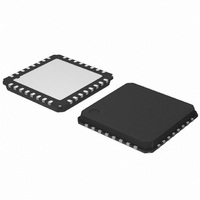
AMIS30532C5321RG ON Semiconductor, AMIS30532C5321RG Datasheet - Page 22

AMIS30532C5321RG
Manufacturer Part Number
AMIS30532C5321RG
Description
IC MOTOR DVR MICRO STEP 32QFP
Manufacturer
ON Semiconductor
Datasheet
1.AMIS30532C5321G.pdf
(29 pages)
Specifications of AMIS30532C5321RG
Package / Case
32-VSQFP
Mounting Type
Surface Mount
Current - Output
1.6A
Voltage - Supply
6 V ~ 30 V
Operating Temperature
-40°C ~ 125°C
Applications
Stepper Motor Driver, 2 Phase
Number Of Outputs
1
Mounting Style
SMD/SMT
Lead Free Status / RoHS Status
Lead free / RoHS Compliant
Voltage - Load
-
Lead Free Status / Rohs Status
Lead free / RoHS Compliant
Available stocks
Company
Part Number
Manufacturer
Quantity
Price
Company:
Part Number:
AMIS30532C5321RG
Manufacturer:
ON Semiconductor
Quantity:
500
Company:
Part Number:
AMIS30532C5321RG
Manufacturer:
ON Semiconductor
Quantity:
10 000
communication between master and AMIS- -30532:
•
•
READ Operation
Registers, it initiates the communication by sending a
bits and a parity check bit The most significant bit (D7)
represents a parity of D[6:0]. If the number of logical ones
in D[6:0] is odd, the parity bit D7 equals “1”. If the number
of logical ones in D[6:0] is even then the parity bit D7 equals
“0”. This simple mechanism protects against noise and
increases the consistency of the transmitted data. If a parity
check error occurs it is recommended to initiate an
additional READ command to obtain the status again.
same routine. Control Registers don’t have a parity check.
successive READ commands as illustrated in Figure 22.
There is however one exception. In case an error condition
is latched in one of Status Registers (see SPI Registers) the
ERRB pin is activated. (See Section Error Output). This
signal flags a problem to the external microcontroller. By
reading the Status Registers information about the root
cause of the problem can be determined. After this READ
operation the Status Registers are cleared. Because the
Status Registers and ERRB pin (see SPI Registers) are only
updated by the internal system clock when the CS line is
Two command types can be distinguished in the
If the Master wants to read data from Status or Control
All 4 Status Registers (see SPI Registers) contain 7 data
Also the Control Registers can be read out following the
The CS line is active low and may remain low between
READ from SPI Register with address ADDR[4:0]:
CMD2 = “0”
WRITE to SPI Register with address ADDR[4:0]:
CMD2 = “1”
Figure 20. Single READ Operation where DATA from SPI register with Address 1 is read by the Master
DO
CS
DI
DATA from previous command or
NOT VALID after POR or RESET
Registers are updated with internal status at the rising
edge of the internal AMIS--30532 clock when CS = 1
OLD DATA or NOT VALID
READ DATA from ADDR 1
COMMAND
DATA
http://onsemi.com
22
READ command. This READ command contains the
address of the SPI register to be read out. At the falling edge
of the eight clock pulse the data- -out shift register is updated
with the content of the corresponding internal SPI register.
In the next 8- -bit clock pulse train this data is shifted out via
DO pin. At the same time the data shifted in from DI
(Master) should be interpreted as the following successive
command or dummy data.
high, the Master should force CS high immediately after the
READ operation. For the same reason it is recommended to
keep the CS line high always when the SPI bus is idle.
WRITE Operation
initiates the communication by sending a WRITE
command. This contains the address of the SPI register to
write to. The command is followed with a data byte. This
incoming data will be stored in the corresponding Control
Register after CS goes from low to high! AMIS- -30532
responds on every incoming byte by shifting out via DO the
data stored in the last received address.
and data) to the Control Register is exactly 16 bits long. If
more or less bits are transmitted the complete transfer packet
is ignored.
(e.g. Status Registers) will not affect the addressed register
and the device operation.
unknown the data shifted out via DO is not valid.
If the Master wants to write data to a Control Register it
It is important that the writing action (command - - address
A WRITE command executed for a read- -only register
Because after a power- -on- -reset the initial address is
COMMAND or DUMMY
DATA from ADDR 1
DATA


