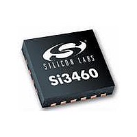
SI3460-E03-GM Silicon Laboratories Inc, SI3460-E03-GM Datasheet - Page 11

SI3460-E03-GM
Manufacturer Part Number
SI3460-E03-GM
Description
IC POWER MANAGEMENT CTLR 11VQFN
Manufacturer
Silicon Laboratories Inc
Datasheet
1.SI3460-E02-GMR.pdf
(24 pages)
Specifications of SI3460-E03-GM
Package / Case
11-VQFN
Applications
Power Sourcing Equipment (PSE)
Current - Supply
500mA
Voltage - Supply
2.7 V ~ 3.6 V
Operating Temperature
-40°C ~ 85°C
Mounting Type
Surface Mount
Product
PoE / LAN Solutions
Supply Voltage (max)
16 V
Supply Voltage (min)
11 V
Operating Temperature Range
- 40 C to + 85 C
Mounting Style
SMD/SMT
Operating Temperature (max)
85C
Operating Temperature (min)
-40C
Pin Count
11
Mounting
Surface Mount
Package Type
QFN EP
Case Length
3mm
Case Height
0.83mm
Screening Level
Industrial
Lead Free Status / RoHS Status
Lead free / RoHS Compliant
Lead Free Status / RoHS Status
Lead free / RoHS Compliant, Lead free / RoHS Compliant
Available stocks
Company
Part Number
Manufacturer
Quantity
Price
Company:
Part Number:
SI3460-E03-GM
Manufacturer:
SAMSUNG
Quantity:
1 400
Company:
Part Number:
SI3460-E03-GM
Manufacturer:
Silicon Laboratories Inc
Quantity:
135
4. Si3460-EVB Functional Description
In combination with low-cost external components, the Si3460 controller provides a complete PSE solution for
embedded PoE applications. Included in the Si3460-EVB reference design is a digital PWM controller-based dc-dc
converter that simplifies overall system design by generating the –48 V PSE supply voltage. An isolated 11 to 16 V
input dc supply is all that is needed to supply the Si3460-EVB reference design. Refer to the Si3460-EVB User’s
Guide and schematics for descriptions in the following sections.
4.1. Reset State
At powerup or if reset is held low, the Si3460 is in an inactive state with the PWM turned off (the switcher FET, M1,
is off) and the pass FET, M2, is off.
4.2. Operating Mode Configuration
At powerup, the Si3460 reads the voltage on the STATUS pin, which is set by a resistor divider from V
ground. The STATUS pin voltage level configures all of the Si3460's operating modes as summarized in Table 8.
After powerup, the STATUS pin drives the base of a PNP transistor that controls an LED. To maintain an accurate
voltage level at the transistor base, it is recommended that the parallel resistance setting the pin voltage be less
than 1 k.
(no resistors populated)
(pullup resistor only)
Pin voltage at V
Pin Voltage
STATUS
< 0.25 V
2.75 V
2.25 V
1.75 V
1.25 V
3.0 V
2.5 V
2.0 V
1.5 V
1.0 V
0.5 V
EE
Supported (W)
Power Level
15.4
15.4
15.4
15.4
7.0
4.0
7.0
4.0
4.0
4.0
7.0
7.0
Table 8. Operating Modes
Classes Supported
All class levels
All class levels
All class levels
All class levels
Class 1 or 2
Class 1 or 2
Class 1 or 2
Class 1 or 2
Class 1
Class 1
Class 1
Class 1
Rev. 1.1
Operating Mode
Midspan/
Endpoint
Endpoint
Endpoint
Endpoint
Endpoint
Endpoint
Endpoint
Midspan
Midspan
Midspan
Midspan
Midspan
Midspan
Auto restart after 2 s
Auto restart after 2 s
Auto restart after 2 s
Auto restart after 2 s
Auto restart after 2 s
Auto restart after 2 s
Restart Action on
Fault or Overload
Event Condition
Restart on RST
Restart on RST
Restart on RST
Restart on RST
Restart on RST
Restart on RST
Si3460
EE
to chip
11


