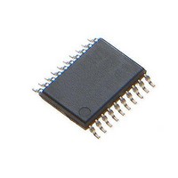
MAX16922AUPE/V+ Maxim Integrated Products, MAX16922AUPE/V+ Datasheet

MAX16922AUPE/V+
Specifications of MAX16922AUPE/V+
Related parts for MAX16922AUPE/V+
MAX16922AUPE/V+ Summary of contents
Page 1
... OUT2 4.7μF V OUT4 4.7μF ________________________________________________________________ Maxim Integrated Products For pricing, delivery, and ordering information, please contact Maxim Direct at 1-888-629-4642, or visit Maxim’s website at www.maxim-ic.com. 2.2MHz, Dual, Step-Down DC-DC ♦ 1.2A High-Efficiency 2.2MHz DC-DC Converter 3.7V to 28V Operating Supply Voltage 45V Load-Dump Protection Output Voltage: 3 ...
Page 2
Dual, Step-Down DC-DC Converters, Dual LDOs, and RESET ABSOLUTE MAXIMUM RATINGS PV1 GND .....................................................-0.3V to +45V LX1 to GND.................................................-0.5V to (PV1 + 0.3V) LX2 to GND.................................................-0.5V to (PV2 + 0.3V) BST to LX1.............................................................-0.3V to +6.0V PV2, PV3, ...
Page 3
Converters, Dual LDOs, and RESET ELECTRICAL CHARACTERISTICS (continued 13.5V PV1 PV2 PV3 OUT1 T = +25°C under normal conditions, unless otherwise noted.) (Note 2) A PARAMETER SYMBOL OUTS1 Discharge Resistance OUT2—SYNCHRONOUS ...
Page 4
Dual, Step-Down DC-DC Converters, Dual LDOs, and RESET ELECTRICAL CHARACTERISTICS (continued 13.5V PV1 PV2 PV3 OUT1 T = +25°C under normal conditions, unless otherwise noted.) (Note 2) A PARAMETER SYMBOL ...
Page 5
Converters, Dual LDOs, and RESET (V = 13.5V PV1 PV2 PV3 OUT1 PV4 OUT1 EFFICIENCY vs. LOAD CURRENT 100 90 80 PV1 = 8V 70 PV1 = 13.5V 60 PV1 = 18V 50 ...
Page 6
Dual, Step-Down DC-DC Converters, Dual LDOs, and RESET (V = 13.5V PV1 PV2 PV3 OUT1 SWITCHING FREQUENCY vs. LOAD CURRENT 2.0 1.6 1.2 0.8 0 200 400 600 800 1000 ...
Page 7
Converters, Dual LDOs, and RESET (V = 13.5V PV1 PV2 PV3 OUT1 PV4 SWITCHING FREQUENCY vs. TEMPERATURE 2.30 2.28 2.26 2.24 2.22 2.20 2.18 2.16 2.14 2.12 2.10 -40 -25 - ...
Page 8
Dual, Step-Down DC-DC Converters, Dual LDOs, and RESET V OUT1 20kΩ RESET GENERATION GND1 LDO REG 1: 300mA PV3 V OUT1 4.7μF OUT3 1.0V TO 4.15V 4.7μF GND2 PWM MODE SELECT LDO REG 2: 300mA PV4 V OUT2 4.7μF ...
Page 9
Converters, Dual LDOs, and RESET TOP VIEW 16 PV4 17 LSUP MAX16922 18 RESET 19 GND1 THIN QFN PIN NAME TQFN TSSOP 1 3 BST Bootstrap Capacitor Input. Connect a 0.1µF ceramic capacitor from BST to LX1. ...
Page 10
Dual, Step-Down DC-DC Converters, Dual LDOs, and RESET PIN NAME TQFN TSSOP 8 10 OUTS2 9 11 PGND2 10 12 LX2 11 13 PV2 12 14 PV3 13 15 OUT3 14 16 GND2 15 17 OUT4 16 18 PV4 ...
Page 11
Converters, Dual LDOs, and RESET Detailed Description The MAX16922 PMIC is designed for medium power level automotive applications requiring multiple sup- plies in a small footprint. As shown in the Typical Applications Circuit , the MAX16922 integrates one high-voltage power ...
Page 12
Dual, Step-Down DC-DC Converters, Dual LDOs, and RESET The MAX16922 limits the peak inductor current sourced by the p-channel MOSFET. When the peak current limit is reached, the internal p-channel MOSFET turns off for the remainder of the cycle. ...
Page 13
Converters, Dual LDOs, and RESET VBAT 0.1μF Applications Information Power-On Sequence When the EN input is pulled high and PV1 is greater than 3.7V (typ), the 5V LSUP linear regulator turns on. Once LSUP exceeds 2.5V, the internal reference and ...
Page 14
Dual, Step-Down DC-DC Converters, Dual LDOs, and RESET Capacitor Selection The input capacitor, CIN1, reduces the current peaks drawn from the supply and reduces switching noise in the MAX16922. The impedance of CIN1 at the switch- ing frequency should ...
Page 15
Converters, Dual LDOs, and RESET High-switching frequencies and relatively large peak currents make PCB layout a very important aspect of design. Good design minimizes excessive EMI on the feedback paths and voltage gradients in the ground plane, both of which ...
Page 16
Dual, Step-Down DC-DC Converters, Dual LDOs, and RESET Chip Information PROCESS: BiCMOS 16 ______________________________________________________________________________________ Package Information For the latest package outline information and land patterns www.maxim-ic.com/packages. Note that a “+”, “#”, or “-” in the package code ...
Page 17
... Maxim cannot assume responsibility for use of any circuitry other than circuitry entirely embodied in a Maxim product. No circuit patent licenses are implied. Maxim reserves the right to change the circuitry and specifications without notice at any time. Maxim Integrated Products, 120 San Gabriel Drive, Sunnyvale, CA 94086 408-737-7600 ____________________ 17 © 2010 Maxim Integrated Products 2 ...


