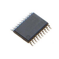
MAX16922AUPE/V+ Maxim Integrated Products, MAX16922AUPE/V+ Datasheet - Page 9

MAX16922AUPE/V+
Manufacturer Part Number
MAX16922AUPE/V+
Description
IC DCDC CONV STPDN LDO 20TSSOP
Manufacturer
Maxim Integrated Products
Datasheet
1.MAX16922ATPAVT.pdf
(17 pages)
Specifications of MAX16922AUPE/V+
Applications
General Purpose
Current - Supply
5µA
Voltage - Supply
3.7 V ~ 28 V
Operating Temperature
-40°C ~ 125°C
Mounting Type
Surface Mount
Package / Case
20-TSSOP Exposed Pad, 20-eTSSOP, 20-HTSSOP
Output Voltage
1.8 V, 2.5 V, 3.3 V, 5 V
Output Current
450 mA, 600 mA, 1.2 A
Switching Frequency
2.2 MHz
Input / Supply Voltage (max)
28 V
Input / Supply Voltage (min)
3.7 V
Maximum Operating Temperature
+ 125 C
Mounting Style
SMD/SMT
Duty Cycle (max)
100 %
Load Regulation
+/- 0.2 %
Minimum Operating Temperature
- 40 C
Number Of Outputs
4
Operating Temperature Range
- 40 C to + 125 C
Supply Current
14 uA
Lead Free Status / RoHS Status
Lead free / RoHS Compliant
TQFN
1
2
3
4
5
6
7
TOP VIEW
PIN
TSSOP
RESET
3
4
5
6
7
8
9
GND1
LSUP
PV4
_______________________________________________________________________________________
EN
16
17
18
19
20
OUTS1
NAME
GND3
+
PWM
GND
BST
PV1
LX1
THIN QFN
MAX16922
Converters, Dual LDOs, and RESET
Bootstrap Capacitor Input. Connect a 0.1µF ceramic capacitor from BST to LX1.
OUT1 Supply Input. Connect a 4.7µF or larger ceramic capacitor from PV1 to PGND.
Ind uctor C onnecti on for OU T1. C onnect a 4.7µH i nd uctor b etw een LX 1 and OU TS 1, and a
S chottky d i od e b etw een LX 1 ( cathod e) and the p ow er - g r ound p l ane ( anod e) as show n i n the
Functi onal D i ag r am .
Ground. Connect GND, GND1, GND2, and GND3 together.
OUT1 Voltage-Sensing Input. Connect OUTS1 directly to the OUT1 output voltage and
bypass to power-ground plane with a minimum total capacitance of 15µF. The total
capacitance can include input bypass capacitors cascaded from OUT1, discharged by a
70Ω resistance between OUTS1 and GND3 when disabled.
PWM Control Input. Connect PWM to OUTS1 to force LX2 to switch every cycle. Connect
PWM to high for forced-PWM operation on OUT2. Connect low for auto-PWM operation to
improve efficiency at light loads.
Ground. Connect GND, GND1, GND2, and GND3 together.
2.2MHz, Dual, Step-Down DC-DC
EP
10
9
8
7
6
LX2
PGND2
OUTS2
GND
PWM
TOP VIEW
FUNCTION
OUTS1
OUTS2
GND1
GND3
PWM
GND
BST
PV1
LX1
EN
10
1
2
3
4
5
6
7
8
9
+
Pin Configurations
MAX16922
TSSOP
Pin Description
EP
20
19
18
17
16
15
14
13
12
11
RESET
LSUP
PV4
OUT4
GND2
OUT3
PV3
PV2
LX2
PGND2
9


