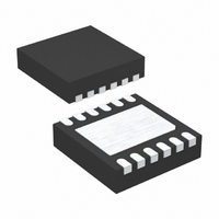
LTC2930HDD#PBF Linear Technology, LTC2930HDD#PBF Datasheet - Page 9

LTC2930HDD#PBF
Manufacturer Part Number
LTC2930HDD#PBF
Description
IC 6 POWER SUPPLY MONITOR 12DFN
Manufacturer
Linear Technology
Datasheet
1.LTC2930HDDPBF.pdf
(12 pages)
Specifications of LTC2930HDD#PBF
Applications
Six Power Supply Monitor
Voltage - Supply
1 V ~ 7 V
Operating Temperature
-40°C ~ 125°C
Mounting Type
Surface Mount
Package / Case
12-DFN
Lead Free Status / RoHS Status
Lead free / RoHS Compliant
Current - Supply
-
Voltage - Input
-
Available stocks
Company
Part Number
Manufacturer
Quantity
Price
APPLICATIONS INFORMATION
connected to the high impedance adjustable input (V4).
V
at ground. The negative trip voltage is calculated from:
In a negative adjustable application, the minimum value for
R4 is limited by the sourcing capability of VREF (±1mA).
With no other load on VREF , R4 (minimum) is:
Tables 2 and 3 offer suggested 1% resistor values for vari-
ous positive and negative supply adjustable applications
assuming 5% monitor thresholds.
Although all six supply monitor comparators have built-
in glitch immunity, bypass capacitors on V1 and V2 are
recommended because the greater of V1 or V2 is also the
V
V6 inputs are allowed.
Power-Down
On power-down, once any of the monitor inputs drops
below its threshold, RST is held at a logic low. A logic low
of 0.4V is guaranteed until both V1 and V2 drop below
1V. If the bandgap reference becomes invalid (V
typical), the LTC2930 will enter the 150μs setup period
when V
Selecting the Reset Timing Capacitor
The reset timeout period is adjustable in order to
accommodate a variety of microprocessor applications.
The reset timeout period, t
a capacitor, C
value of this capacitor is determined by:
REF
CC
V
C
1.210V
TRIP
for the device. Filter capacitors on the V3, V4, V5 and
RT
1mA
provides the necessary level shift required to operate
CC
=
= −V
2MΩ
t
rises above 2.4V max.
RST
= 1.210k
REF
RT
= 500 pF / ms
, between the CRT pin and ground. The
•
R3
R4
[
;V
REF
RST
= 1.210V
, is adjusted by connecting
]
• t
RST
Nominal
CC
< 2V
Leaving the CRT pin unconnected generates a minimum
reset timeout of approximately 25μs. Maximum reset
timeout is limited by the largest available low leakage
capacitor. The accuracy of the timeout period is affected
by capacitor leakage (the nominal charging current is 2μA)
and capacitor tolerance. A low leakage ceramic capacitor
is recommended.
OR-ed System Reset
In Figure 5, two LTC2930s are confi gured to monitor 11
supply voltages simultaneously. The unused adjustable
input pin is tied to the V1 input. The open-drain RST
outputs are OR-tied and pulled up to 5V through a 10kΩ
resistor. RST pulls high 94ms after all the inputs are above
the threshold voltages. Should a reset event occur on ei-
ther LTC2930, both RST outputs pull low. Similarly, if the
manual reset pushbutton is pressed, both RST outputs
also pull low.
Using a Pushbutton On/Off Controller with the
LTC2930
In Figure 6, the LTC2950-1 pushbutton controller powers
a system on and off. The system starts after the pushbut-
ton is pressed, which brings the LTM4600’s RUN pin high.
Subsequently, the LTM4600 generates a 5V output which
applies power to each of the four DC/DC converters.
The LTC2930 is confi gured to mode 13 (see Table 1).
The voltages monitored are 5V, 3.3V, 1.8V, –5.2V, 2.5V
and 12V.
If the KILL input is not driven high within 512ms of a valid
turn-on event, EN pulls low shutting down the system. If
the external 12V supply drops below 9.6V, EN pulls low,
powering down the LTM4600 and subsequent circuitry.
An external 4.7nF capacitor sets the 9.4ms reset timeout
period. Therefore, 9.4ms after the last supply is above
threshold, RST pulls high. The reset timing capacitor
must be chosen to keep the reset timeout period below
512ms. Otherwise, the KILL timer will expire and shut
down the system.
Pressing the pushbutton after the system is powered initi-
ates the power off sequence. An interrupt is set, bringing
EN low immediately and disabling the LTM4600.
LTC2930
2930fa
9


