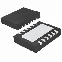
LTC2938CDE#TRPBF Linear Technology, LTC2938CDE#TRPBF Datasheet - Page 13

LTC2938CDE#TRPBF
Manufacturer Part Number
LTC2938CDE#TRPBF
Description
IC FOUR PWR SUPPLY MONITOR 12DFN
Manufacturer
Linear Technology
Datasheet
1.LTC2939CMSPBF.pdf
(20 pages)
Specifications of LTC2938CDE#TRPBF
Applications
Four Power Supply Monitor
Voltage - Supply
1 V ~ 5 V
Operating Temperature
0°C ~ 70°C
Mounting Type
Surface Mount
Package / Case
12-DFN
Lead Free Status / RoHS Status
Lead free / RoHS Compliant
Current - Supply
-
Voltage - Input
-
Available stocks
Company
Part Number
Manufacturer
Quantity
Price
APPLICATIONS INFORMATION
Power-Down
On power-down, once any of the monitor inputs drops
below its threshold, RST is held at a logic low. A logic low
of 0.4V is guaranteed until both V1 and V2 drop below
1V. If the bandgap reference becomes invalid (V
typical), the LTC2938/LTC2939 will reconfi gure when V
rises above 2.4V (max).
Selecting the Reset Timing Capacitor
The reset timeout period is adjustable in order to accom-
modate a variety of microprocessor applications. The reset
timeout period, t
C
is determined by:
Leaving CRT unconnected generates a minimum reset
timeout period of approximately 20μs. The maximum
reset timeout period is limited by the largest available low
leakage capacitor. The accuracy of the timeout period is
affected by capacitor leakage (the nominal charging current
is 2μA) and capacitor tolerance. A low leakage ceramic
capacitor is recommended.
Watchdog Timer
The watchdog circuit typically monitors a microprocessor’s
activity. The microprocessor is required to change the
logic state of the WDI input on a periodic basis in order
to clear the watchdog timer. Whenever an undervoltage
condition exists, the watchdog timer is cleared and WDO
is set high. The watchdog timer starts when RST pulls
high. Subsequent edges received on the WDI input clear
the watchdog timer. If uncleared, the watchdog timer
continues to run until it times out. Once it times out,
internal circuitry brings the WDO and RST outputs low.
WDO remains low for at least one reset timeout period
and can then be cleared by a new edge on the WDI input
or anytime an undervoltage condition occurs.
The watchdog timer may be disabled in three ways. One
method is to simply ground CWT. With CWT held at ground,
any undervoltage event forces WDO high indefi nitely. A
second method is to leave the WDI input fl oating or in high
RT
C
, between CRT and ground. The value of this capacitor
RT
=
2
t
RST
M
Ω
RST
=
, is adjusted by connecting a capacitor,
500
⎛
⎝ ⎜
ms
pF
⎞
⎠ ⎟
•
t
RST
CC
< 2V
CC
impedance. The last method is to continuously drive WDI
between the low and high thresholds.
Selecting the Watchdog Timing Capacitor
The watchdog timeout period is adjustable and can be
optimized for software execution. The watchdog timeout
period, t
between CWT and ground. The value of this capacitor is
determined by:
Leaving CWT unconnected generates a minimum watchdog
timeout period of approximately 200μs. The maximum
watchdog timeout period is limited by the largest available
low leakage capacitor. The accuracy of the timeout period
is affected by capacitor leakage (the nominal charging
current is 2μA) and capacitor tolerance. A low leakage
ceramic capacitor is recommended.
Pull-Up Resistors for WDO and RST
The WDO and RST pins provide weak pull-up currents to
V2. This current is typically greater than 6μA when V2 is
greater than 3.3V. The magnitude of the pull-up current
decreases as V2 decreases. For V2 confi gured to monitor
2.5V, 1.8V, 1.5V and 1.2V supplies, external pull-up resistors
are required from both pins to the interface logic supply
to ensure that the output high voltage is above the V
input threshold of the external circuit. The WDO and RST
pins can be pulled to voltages higher than V2 by external
pull-up resistors.
Watchdog Application
Figure 5 shows a typical application for the LTC2938/
LTC2939. The C
dog timeout period for optimal software execution. If
the software malfunctions and the state of the WDI pin
is unchanged before the end of the watchdog timeout
period (t
to a low state. At the same time, RST is pulled low to reset
the microprocessor. While RST is low, the WDI pin does
not affect RST or WDO. The system therefore resets for
at least t
C
WT
WD
=
RST
WD
, is adjusted by connecting a capacitor, C
20
.
), the LTC2938/LTC2939 WDO pin is latched
t
WD
M
Ω
WT
=
timing capacitor adjusts the watch-
LTC2938/LTC2939
50
⎛
⎝ ⎜
ms
pF
⎞
⎠ ⎟
•
t
WD
13
293839ff
WT
OH
,


