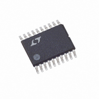
LTC2922IF#TRPBF Linear Technology, LTC2922IF#TRPBF Datasheet - Page 6

LTC2922IF#TRPBF
Manufacturer Part Number
LTC2922IF#TRPBF
Description
IC 5 PWR SUPPLY MONITOR 20TSSOP
Manufacturer
Linear Technology
Datasheet
1.LTC2921CGN-3.3.pdf
(20 pages)
Specifications of LTC2922IF#TRPBF
Applications
Five Power Supply Monitor
Voltage - Supply
4.5 V ~ 5.5 V
Current - Supply
2mA
Operating Temperature
-40°C ~ 85°C
Mounting Type
Surface Mount
Package / Case
20-TSSOP
Lead Free Status / RoHS Status
Lead free / RoHS Compliant
Voltage - Input
-
Available stocks
Company
Part Number
Manufacturer
Quantity
Price
PI FU CTIO S
LTC2921/LTC2922 Series
S0, D0 (Pins 1, 20 [LTC2922]): Remote Switch 0. These
pins are the terminals of an internal N-channel FET switch
that is enabled after the GATE pin is fully ramped up. This
switch can be used to connect a remote sense line to
compensate for IR drop across the external FETs. The gate
of the internal switch ramps up at a nominal rate of 8V/ms.
The pins are interchangeable, either switch pin can be tied
to the load side. Tie both pins to ground if unused.
S4, D4 (Pins 7, 8 [LTC2922]): Remote Sense Switch 4. Tie
to GND if unused.
S3, D3 (Pins 5, 6/Pins 9, 10): Remote Sense Switch 3. Tie
to GND if unused.
S2, D2 (Pins 7, 8/Pins 11, 12): Remote Sense Switch 2.
Tie to GND if unused.
S1, D1 (Pins 9, 10/Pins 13, 14): Remote Sense Switch 1.
Tie to GND if unused.
TIMER (Pin 16/Pin 2): Timing Delay Input. Connect a
capacitor between this pin and ground to set a 600ms/ F
delay at two points in the monitoring sequence. This sets
the delay after all monitors are good, before the start of
GATE ramping, and the delay after the remote sense
switches are on, before PG is activated. TIMER must fall
below 150mV before a timing delay can start. The TIMER
pin is pulled to ground at other points in the sequence.
V1-V4 (Pins 1-4/Pins 3-6): Supply Monitor Inputs. All four
inputs must lie above the monitor threshold level (0.5V)
and below the monitor overvoltage level (0.7V) for a turn-
on sequence to commence or continue. When any monitor
input falls outside those levels, the GATE and PG pins are
pulled low, disconnecting all the loads. Glitch filtering on
the 0.5V monitor threshold prevents low-energy voltage
spikes from affecting the comparators’ results. V1 also
serves as an active-low reset pin for the circuit breaker. Tie
unused monitor inputs to used monitor inputs.
6
U
U
U
(LTC2921/LTC2922 or [LTC2922 Only])
GND (Pin 11/Pin 15): Circuit Ground.
PG (Pin 12/Pin 16): Power Good Output. A 4 A current
source from the internal charge pump rail (V
PG up after the turn-on sequence is complete. The output
is pulled to ground before turn-on is complete, when any
monitor is out of compliance, when the circuit breaker
trips, and when V
can be added to pull up to a lower voltage and to improve
pull up speed. This pin can also be configured as a gate
drive for external N-channel FETs in sequencing applica-
tions. In applications not requiring the PG output, leave the
pin unconnected.
GATE (Pin 13/Pin 17): Gate Drive for External N-Channel
FETs. A 10 A current source from the internal charge
pump rail (V
channel MOSFETs forcing all supplies to track on. The
resistor and capacitor network from this pin to ground
sets the supplies’ ramp rate and enhances control loop
stability.
SENSE (Pin 14/Pin 18): Circuit Breaker Sense Input. An
external resistor between V
tronic circuit breaker trip current. The breaker trips when
the voltage across the resistor exceeds 50mV for 1 s. To
disable the circuit breaker tie SENSE to V
circuit breaker after the current falls below the trip point,
pull the V1 pin below 0.5V for >150 s or go into
undervoltage lockout for >10 s.
V
monitored through an internal resistive divider in a man-
ner similar to the V1-V4 inputs. An undervoltage lockout
circuit disables the part until the voltage at V
than 2.2V. The V
supply voltage. Bypass the V
capacitor.
CC
(Pin 15/Pin 19): Supply Voltage. The voltage at V
PUMP
CC
CC
) ramps the gates of the external N-
pin must be connected to the highest
is undervoltage. An external resistor
CC
CC
and SENSE sets the elec-
pin to ground with a 10 F
CC
. To reset the
CC
PUMP
is greater
) pulls
29212fa
CC
is


