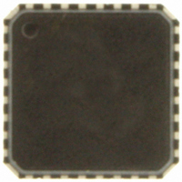
ADT7462ACPZ-5RL7 ON Semiconductor, ADT7462ACPZ-5RL7 Datasheet - Page 40

ADT7462ACPZ-5RL7
Manufacturer Part Number
ADT7462ACPZ-5RL7
Description
IC TEMP/VOLT MONITOR 32-LFCSP
Manufacturer
ON Semiconductor
Datasheet
1.ADT7462ACPZ-5RL7.pdf
(81 pages)
Specifications of ADT7462ACPZ-5RL7
Function
Fan Control, Temp Monitor
Topology
ADC, Comparator, Multiplexer, Register Bank
Sensor Type
External & Internal
Sensing Temperature
-40°C ~ 125°C, External Sensor
Output Type
SMBus™
Output Alarm
No
Output Fan
Yes
Voltage - Supply
3 V ~ 5.5 V
Operating Temperature
-40°C ~ 125°C
Mounting Type
Surface Mount
Package / Case
32-LFCSP
Supply Voltage (max)
5.5 V
Supply Voltage (min)
3 V
Maximum Operating Temperature
+ 125 C
Minimum Operating Temperature
- 40 C
Lead Free Status / RoHS Status
Lead free / RoHS Compliant
Other names
ADT7462ACPZ-500RL7
ADT7462ACPZ-500RL7
ADT7462ACPZ-500RL7TR
ADT7462ACPZ-500RL7TR
ADT7462ACPZ-5RL7TR
ADT7462ACPZ-500RL7
ADT7462ACPZ-500RL7TR
ADT7462ACPZ-500RL7TR
ADT7462ACPZ-5RL7TR
Available stocks
Company
Part Number
Manufacturer
Quantity
Price
Company:
Part Number:
ADT7462ACPZ-5RL7
Manufacturer:
ON Semiconductor
Quantity:
135
Step 7—T
the temperature measured has dropped back below T
before the fan turns off. The premise for temperature
hysteresis (T
chatter or cycle on and off regularly whenever the
temperature hovers near the T
needed for the system to cool down or heat up as the fan is
turning on and off. Values of hysteresis are programmable in
the range of 1°C to 15°C. Larger values of T
fans from chattering on and off. The T
set at 4°C.
Hysteresis Register
Register 0x60, Bits [3:0] Local HYS
Register 0x61, Bits [3:0] Remote 1 HYS
Register 0x62, Bits [3:0] Remote 2 HYS
Register 0x63, Bits [3:0] Remote 3 HYS
below T
the PWM1, PWM2 Frequency Register (0x25) and the
PWM3, PWM4 Frequency Register (0x26) allow the fans to
be turned off or to be kept spinning below T
are always on, the T
the temperature drops below T
T
The T
In some applications, it is required that fans not turn off
Figure 63. How T
HYST
Figure 64. T
MIN
HYST
is the amount of extra cooling a fan provides after
HYST
100%
100%
HYST
but remain running at PWM
0%
0%
value chosen determines the amount of time
for Temperature Channels
T
HYST
) is that without it, the fan would merely
HYST
HYST
T
T
THERM
MIN
MIN
Value Applies to Fan On/Off
Hysteresis
value has no effect on the fan when
Control
Relates to Automatic Fan
HYSTERESIS
MIN
T
T
MIN
RANGE
RANGE
setting.
.
T
T
THERM
THERM
HYST
MIN
HYST
default value is
MIN
. Bits [1:0] of
. If the fans
prevent the
http://onsemi.com
MIN
40
Dynamic T
described in the Automatic Fan Control Overview section,
the ADT7462 has a mode that extends the basic automatic
fan speed control loop. Dynamic T
ADT7462 to intelligently adapt the system’s cooling
solution for best system performance or lowest possible
system acoustics, depending on user or design requirements.
Use of dynamic T
for worst−case conditions and significantly reduces system
design and validation time.
Designing for Worst−Case Conditions
conditions. In PC design, the worst−case conditions include,
but are not limited to, the following:
•
•
•
In addition to the automatic fan speed control mode
System design must always allow for worst−case
Worst−Case Altitude
A computer can be operated at different altitudes.
Altitude affects the relative air density, which alters the
effectiveness of the fan cooling solution. For example,
when comparing 40°C air temperature at 10,000 feet to
20°C air temperature at sea level, relative air density is
increased by 40%. This means that the fan can spin
40% slower and make less noise at sea level than at
10,000 feet while keeping the system at the same
temperature at both locations.
Worst−Case Fan
Due to manufacturing tolerances, fan speeds in rpm are
normally quoted with a tolerance of ±20%. The
designer must assume that the fan rpm can be 20%
below tolerance. This translates to reduced system
airflow and elevated system temperature. Note that fans
20% out of tolerance can negatively impact system
acoustics because they run faster and generate more
noise.
Worst−Case Chassis Airflow
The same motherboard can be used in a number of
different chassis configurations. The design of the
chassis and the physical location of fans and
components determine the system’s thermal
characteristics. Moreover, for a given chassis, the
addition of add−in cards, cables, or other system
configuration options can alter the system airflow and
reduce the effectiveness of the system cooling solution.
The cooling solution can also be inadvertently altered
by the end user. (For example, placing a computer
against a wall can block the air ducts and reduce system
airflow.)
MIN
Control Mode
MIN
control alleviates the need to design
MIN
control allows the


