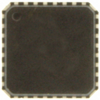
ADT7462ACPZ-5RL7 ON Semiconductor, ADT7462ACPZ-5RL7 Datasheet - Page 48

ADT7462ACPZ-5RL7
Manufacturer Part Number
ADT7462ACPZ-5RL7
Description
IC TEMP/VOLT MONITOR 32-LFCSP
Manufacturer
ON Semiconductor
Datasheet
1.ADT7462ACPZ-5RL7.pdf
(81 pages)
Specifications of ADT7462ACPZ-5RL7
Function
Fan Control, Temp Monitor
Topology
ADC, Comparator, Multiplexer, Register Bank
Sensor Type
External & Internal
Sensing Temperature
-40°C ~ 125°C, External Sensor
Output Type
SMBus™
Output Alarm
No
Output Fan
Yes
Voltage - Supply
3 V ~ 5.5 V
Operating Temperature
-40°C ~ 125°C
Mounting Type
Surface Mount
Package / Case
32-LFCSP
Supply Voltage (max)
5.5 V
Supply Voltage (min)
3 V
Maximum Operating Temperature
+ 125 C
Minimum Operating Temperature
- 40 C
Lead Free Status / RoHS Status
Lead free / RoHS Compliant
Other names
ADT7462ACPZ-500RL7
ADT7462ACPZ-500RL7
ADT7462ACPZ-500RL7TR
ADT7462ACPZ-500RL7TR
ADT7462ACPZ-5RL7TR
ADT7462ACPZ-500RL7
ADT7462ACPZ-500RL7TR
ADT7462ACPZ-500RL7TR
ADT7462ACPZ-5RL7TR
Available stocks
Company
Part Number
Manufacturer
Quantity
Price
Company:
Part Number:
ADT7462ACPZ-5RL7
Manufacturer:
ON Semiconductor
Quantity:
135
of 2. In this instance, the fan takes about 17.6 seconds to
reach full running speed.
temperature with the slowest ramp rate. The ramp rate is set
to 1, while all other control parameters remain the same.
With the slowest ramp rate selected, it takes 35 seconds for
the fan to reach full speed.
reacts to temperature change is dependent on the ramp rate
selected in the enhanced acoustics registers. The higher the
ramp rate, the faster the fan reaches the newly calculated fan
speed.
temperature varies. As the temperature increases, the fan
speed ramps up. Small drops in temperature do not affect the
ramp−up function, because the newly calculated fan speed
is still higher than the previous PWM value. Enhanced
acoustics mode allows the PWM output to be made less
sensitive to temperature variations. This is dependent on the
ramp rate selected and programmed into the enhanced
acoustics registers.
Figure 79 shows the PWM output response for a ramp rate
Figure 80 shows how the control loop reacts to
As Figure 77 to Figure 80 show, the rate at which the fan
Figure 81 shows the behavior of the PWM output as
Figure 79. Enhanced Acoustics Mode with Ramp
Figure 80. Enhanced Acoustics Mode with Ramp
140
120
100
120
100
80
60
40
20
80
60
40
20
0
0
0
0
R
TEMP
R
TEMP
(5C)
(5C)
Rate = 2
Rate = 1
TIME (s)
TIME (s)
PWM DUTY CYCLE (%)
PWM DUTY CYCLE (%)
17.6
35
http://onsemi.com
120
100
80
60
40
20
0
140
120
100
80
60
40
20
0
48
Slower Ramp Rates
times by slowing the ramp rates. Each ramp rate can be
slowed by a factor of 4.
PWM1 Configuration Register (0x21)
PWM2 Configuration Register (0x22)
PWM3 Configuration Register (0x23)
PWM4 Configuration Register (0x24)
configuration registers slows the ramp rate for PWM1 to
PWM4 by 4.
Fan Freewheeling Test Mode
whether fans connected to the ADT7462 are working
properly. It is particularly useful where fans coupled in the
duct can affect the airflow of another fan. If one fan has
failed, it may not be apparent, because moving air from other
fans can cause air to flow through the faulty fan, which in
turn can cause the faulty fan to rotate.
primary and redundant setup. In such a system, the
following setup is recommended. The primary fans are
Fan 1, Fan 2, Fan 3, and Fan 4. The redundant fans are Fan 5,
Fan 6, Fan 7, and Fan 8. In this setup, each primary and
redundant fan can be driven separately because they are
driven by different PWMs.
Figure 81. How Fan Reacts to Temperature Variations
The ADT7462 can be programmed for much longer ramp
Setting Bit 3 (the SLOW bit) to 1 in the PWM1 to PWM4
The fan freewheeling test mode is intended to diagnose
The fan freewheeling test is most useful in a system using
PWM 1
PWM 3
Figure 82. Fan Freewheeling Test Mode Setup
90
80
70
60
50
40
30
20
10
TACH CCT 1
0
FAN 1
FAN 5
in Enhanced Acoustics Mode
TACH CCT 2
FAN 2
FAN 6
R
TACH CCT 3
TEMP
FAN 3
FAN 7
PWM DUTY CYCLE (%)
(5C)
TACH CCT 4
FAN 4
FAN 8
PWM 2
PWM 4


