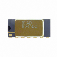
AD594ADZ Analog Devices Inc, AD594ADZ Datasheet - Page 8

AD594ADZ
Manufacturer Part Number
AD594ADZ
Description
IC THERMOCOUPLE INSTR AMP 14CDIP
Manufacturer
Analog Devices Inc
Datasheet
1.AD595AQ.pdf
(8 pages)
Specifications of AD594ADZ
Function
Thermocouple Amplifier
Topology
Ice Point Compensation, Overload Detection
Sensor Type
External
Output Type
Voltage
Output Alarm
Yes
Output Fan
No
Voltage - Supply
5 V ~ ±15 V
Operating Temperature
-55°C ~ 125°C
Mounting Type
Through Hole
Package / Case
14-CDIP (0.300", 7.62mm)
Temperature Sensor Function
Temp Sensor
Operating Temperature (max)
125C
Operating Temperature Classification
Military
Operating Supply Voltage (typ)
5V
Operating Supply Voltage (max)
5.5V
No. Of Amplifiers
2
Input Offset Voltage
16µV
Bandwidth
15kHz
Amplifier Output
Single Ended
Supply Voltage Range
5V To ± 15V
Supply Current
160µA
Amplifier Case Style
TO-116
Rohs Compliant
Yes
Lead Free Status / RoHS Status
Lead free / RoHS Compliant
Sensing Temperature
-
Lead Free Status / Rohs Status
Compliant
AD594/AD595
THERMOCOUPLE BASICS
Thermocouples are economical and rugged; they have reason-
ably good long-term stability. Because of their small size, they
respond quickly and are good choices where fast response is im-
portant. They function over temperature ranges from cryogenics
to jet-engine exhaust and have reasonable linearity and accuracy.
Because the number of free electrons in a piece of metal de-
pends on both temperature and composition of the metal, two
pieces of dissimilar metal in isothermal and contact will exhibit
a potential difference that is a repeatable function of tempera-
ture, as shown in Figure 14. The resulting voltage depends on
the temperatures, T1 and T2, in a repeatable way.
Since the thermocouple is basically a differential rather than
absolute measuring device, a know reference temperature is
required for one of the junctions if the temperature of the other
is to be inferred from the output voltage. Thermocouples made
of specially selected materials have been exhaustively character-
ized in terms of voltage versus temperature compared to primary
temperature standards. Most notably the water-ice point of 0 C
is used for tables of standard thermocouple performance.
An alternative measurement technique, illustrated in Figure 15,
is used in most practical applications where accuracy requirements
do not warrant maintenance of primary standards. The reference
junction temperature is allowed to change with the environment
of the measurement system, but it is carefully measured by some
type of absolute thermometer. A measurement of the thermo-
couple voltage combined with a knowledge of the reference
temperature can be used to calculate the measurement junction
temperature. Usual practice, however, is to use a convenient
thermoelectric method to measure the reference temperature
Figure 14. Thermocouple Voltage with 0 C Reference
TEMPERATURE
0.035 0.010
(0.89 0.25)
0.125
(3.18)
UNKNOWN
(1.02) R
MIN
0.040
0.047 0.007
(1.19 0.18) 0.017
T1
14
CONSTANTAN
1
PIN 1
(
0.430 (10.92)
(17.78 0.25)
0.43 +0.08
0.700 0.010
+0.003
–0.002
–0.05
TO-116 (D) Package
Cu
(
(2.54)
0.100
BSC
IRON
8
7
0.265
(6.73)
0.085 (2.16)
Cu
0.180 0.030
(4.57 0.76)
CONSTANTAN
V1
0.290 0.010
(7.37 0.25)
0.30 (7.62) REF
(7.87 0.25)
0.31 0.01
T2
Dimensions shown in inches and (mm).
REFERENCE
ICE POINT
OUTLINE DIMENSIONS
0.095 (2.41)
0.01 0.002
(0.25 0.05)
–8–
and to arrange its output voltage so that it corresponds to a ther-
mocouple referred to 0 C. This voltage is simply added to the
thermocouple voltage and the sum then corresponds to the stan-
dard voltage tabulated for an ice-point referenced thermocouple.
The temperature sensitivity of silicon integrated circuit transis-
tors is quite predictable and repeatable. This sensitivity is
exploited in the AD594/AD595 to produce a temperature re-
lated voltage to compensate the reference of “cold” junction of a
thermocouple as shown in Figure 16.
Since the compensation is at the reference junction temperature,
it is often convenient to form the reference “junction” by connect-
ing directly to the circuit wiring. So long as these connections
and the compensation are at the same temperature no error will
result.
3.175)
0.125
(0.812)
MIN
(7.87)
0.032
0.310
Figure 15. Substitution of Measured Reference
Temperature for Ice Point Reference
14
Figure 16. Connecting Isothermal Junctions
CONSTANTAN
T1
1
T1
PIN 1
(19.55 0.39)
0.600 (15.24)
0.77 0.015
(0.457)
0.018
BSC
CONSTANTAN
Cu
IRON
Cerdip (Q) Package
IRON
8
7
V2
0.100
(2.54)
BSC
0.260 0.020
(6.6 0.51)
0.035 0.010
(0.889 0.254)
V1
'
Cu
SEATING
PLANE
0.180 0.030
(4.57 0.76)
CuNi–
Cu
Cu
V1
T3
15
T3
0
0.300 (7.62)
V
FOR PROPERLY
SCALED V
1
REF
'
= V
0.010 0.001
(0.254 0.025)
1
3
'
= f(T
V3
0.148 0.015
(3.76 0.38)
'
3
)
REV. C


