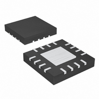
MAX6639ATE+T Maxim Integrated Products, MAX6639ATE+T Datasheet - Page 10

MAX6639ATE+T
Manufacturer Part Number
MAX6639ATE+T
Description
IC TEMP MONITOR 2CH 16-TQFN
Manufacturer
Maxim Integrated Products
Datasheet
1.MAX6639AEE.pdf
(22 pages)
Specifications of MAX6639ATE+T
Function
Fan Control, Temp Monitor
Topology
ADC, PWM Generator, Tach Counter
Sensor Type
External & Internal
Sensing Temperature
0°C ~ 150°C, External Sensor
Output Type
I²C™/SMBus™
Output Alarm
Yes
Output Fan
Yes
Voltage - Supply
3 V ~ 3.6 V
Operating Temperature
-40°C ~ 125°C
Mounting Type
Surface Mount
Package / Case
16-TQFN Exposed Pad
Lead Free Status / RoHS Status
Lead free / RoHS Compliant
2-Channel Temperature Monitor with Dual,
Automatic, PWM Fan-Speed Controller
are 30h to 60h. Set the value to correspond to the full-
rated RPM of the fan. See Figure 4.
Figure 5 shows how the MAX6639 calculates the target
tachometer value based on the measured temperature.
At T
sponding to the maximum tachometer count value
stored in register 22h or 23h. Bit 0 of register 11h (fan
1) and register 15h (fan 2) selects the behavior below
T
below T
drop 5°C below T
set to 1, the fan does not turn off below T
instead stays at the maximum tachometer count in reg-
ister 22h or 23h.
When the measured temperature is higher than T
the MAX6639 calculates the target tachometer count
value based on two linear equations. The target
tachometer count decreases by the tach step size
value stored in bits 7 through 4 of registers 11h and
15h each time the measured temperature increases by
the temperature step size value stored in bits 2 and 3 of
registers 11h and 15h. As the measured temperature
continues to increase, a second tachometer step size
goes into effect. Bits 3 through 0 of register 12h and
16h select the number temperature/PWM steps after
which the new step size takes effect. The new step size
is selected by bits 7 to 4 of registers 12h and 16h.
Figure 4. Tachometer Target Calculation
10
MIN
TACH
TACH
0xFFh
MIN
. If bit 0 is equal to zero, the fan is completely off
______________________________________________________________________________________
MAX
MIN
, the fan spins at a minimum speed value corre-
MIN
TACH
. When the temperature is falling, it must
T
MIN-5
MIN
before the fan turns off. If bit 0 is
T
MIN
TACH
A+1
T
B
TACH
TEMPERATURE
B+1
MIN
, but
MIN
,
These registers contain the results of temperature mea-
surements. The MSB has a weight of +128°C and the
LSB +1°C. Temperature data for remote diode 1 is in
the channel 1 temperature register. Temperature data
for remote diode 2 or the local sensor (selectable by bit
4 in the global configuration register) is in the channel 2
temperature register. Three additional temperature bits
provide resolution down to 0.125°C and are in the
channel 1 extended temperature (05h) and channel 2
extended temperature (06h) registers. The channel 1
and channel 2 temperature registers do not update until
at least 250ms after the access of the associated
extended temperature registers. All values below 0°C
return 00h.
A 1 indicates that an ALERT, THERM, OT, or fan fault has
occurred. Reading this register clears bits 7, 6, 1, and 0.
Reading the register also clears the ALERT and
FANFAIL outputs, but not the THERM and OT outputs. If
the fault is still present on the next temperature measure-
ment cycle, any cleared bits and outputs are set again. A
successful alert response clears the values on the out-
puts but does not clear the status register bits. The
ALERT bits assert when the measured temperature is
higher than the respective thresholds. The THERM and
OT outputs behave like comparators with 5°C hysteresis.
Figure 5. RPM Target Calculation
RPM
RPM
MAX
MIN
Channel 1 and Channel 2 Temperature Registers
0
RPM
T
MIN
-5
T
MIN
TACH
Register Descriptions
A+1
Status Register (02h)
TACH
T
B
B+1
(00h and 01h)
TEMPERATURE


