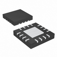
MAX6639ATE+T Maxim Integrated Products, MAX6639ATE+T Datasheet - Page 13

MAX6639ATE+T
Manufacturer Part Number
MAX6639ATE+T
Description
IC TEMP MONITOR 2CH 16-TQFN
Manufacturer
Maxim Integrated Products
Datasheet
1.MAX6639AEE.pdf
(22 pages)
Specifications of MAX6639ATE+T
Function
Fan Control, Temp Monitor
Topology
ADC, PWM Generator, Tach Counter
Sensor Type
External & Internal
Sensing Temperature
0°C ~ 150°C, External Sensor
Output Type
I²C™/SMBus™
Output Alarm
Yes
Output Fan
Yes
Voltage - Supply
3 V ~ 3.6 V
Operating Temperature
-40°C ~ 125°C
Mounting Type
Surface Mount
Package / Case
16-TQFN Exposed Pad
Lead Free Status / RoHS Status
Lead free / RoHS Compliant
This register masks the ALERT, OT, THERM, and
FANFAIL outputs. A 1 prevents the corresponding fail-
ures from being asserted on these outputs. The mask
bits do not affect the status register.
The global configuration register controls the shutdown
mode, power-on reset, SMBus timeout, and tempera-
ture channel 2 source select:
• D7: Run/Standby. Normal operation is run (0).
• D6: Software POR. Writing a 1 resets all registers to
• D5: SMBus Timeout Disable. Writing a zero enables
• D4: Temperature Channel 2 Source. Selects either
Table 4. Register Map (continued)
READ/
WRITE
R/W
R/W
Setting this bit to 1 suspends conversions and puts
the MAX6639 into low-power sleep mode.
their default values.
SMBus timeout for prevention of bus lockup. When
the timeout function is enabled, the SMBus interface
is reset if SDA or SCL remains low for more than
74ms (typ).
local or remote 2 as the source for temperature chan-
W
W
R
R
R
R
REGISTER
ADDRESS
3Dh
NO.
3Eh
26h
27h
27h
28h
29h
3Fh
2-Channel Temperature Monitor with Dual,
Global Configuration Register (04h)
______________________________________________________________________________________
STATE
POR
0011
1100
0000
0000
0011
1100
0100
0100
0000
0101
1000
0100
1101
0000
0000
000
Automatic, PWM Fan-Speed Controller
Fan 2 current
manufacturer
Read device
Read device
Fan 1 target
Fan 2 target
temperature
temperature
FUNCTION
duty cycle
duty cycle
duty cycle
Channel 1
Channel 2
minimum
minimum
fan-start
fan-start
revision
Read
ID
ID
Mask Register (03h)
MSB
MSB
MSB
MSB
MSB
D7
0
0
0
D6
—
—
—
—
—
1
1
0
• D3: PWM Output Frequency Range. Selects either
These registers contain the extended temperature data
from channels 1 and 2. Bits D[7:5] contain the 3 LSBs
of the temperature data. The bit values are 0.5°C,
0.25°C, and 0.125°C. When bit 0 is set to 1, a diode
fault has been detected.
These registers contain the temperatures above which
the ALERT, THERM, and OT status bits set and outputs
assert (for the temperature channels that are not
masked). The data format is the same as that of the
channel 1 and channel 2 temperature registers: the
LSB weight is +1°C and the MSB is +128°C.
D5
—
—
—
—
—
0
0
0
nel 2 register data. Writing a zero to this bit selects
remote 2 for temperature channel 2.
the 20Hz to 100Hz range or the 5kHz to 25kHz range
for the PWM outputs (see Table 9).
Channel 1 and Channel 2 ALERT, OT, and THERM
Extended Temperature Registers (05h and 06h)
D4
—
—
—
—
—
1
0
0
D3
—
—
—
—
—
1
1
0
Limits (08h Through 0Dh)
D2
—
—
—
—
—
0
1
0
D1
—
—
—
—
—
0
0
0
LS B
LS B
LS B
LS B
LS B
D 0
0
1
0
13


