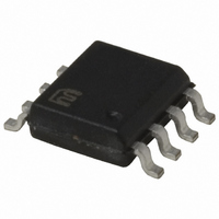
MIC284-3BM TR Micrel Inc, MIC284-3BM TR Datasheet - Page 6

MIC284-3BM TR
Manufacturer Part Number
MIC284-3BM TR
Description
IC SUPERVISOR THERM 2ZONE 8-SOIC
Manufacturer
Micrel Inc
Series
SilentSense™r
Datasheet
1.MIC284-0YM.pdf
(20 pages)
Specifications of MIC284-3BM TR
Function
Temp Monitoring System (Sensor)
Topology
ADC (Sigma Delta), Comparator, Register Bank
Sensor Type
External & Internal
Sensing Temperature
-55°C ~ 125°C, External Sensor
Output Type
I²C™/SMBus™
Output Alarm
Yes
Output Fan
Yes
Voltage - Supply
2.7 V ~ 5.5 V
Operating Temperature
-55°C ~ 125°C
Mounting Type
Surface Mount
Package / Case
8-SOIC (3.9mm Width)
Lead Free Status / RoHS Status
Contains lead / RoHS non-compliant
Other names
MIC284-3BMTR
MIC284-3BMTR
MIC284-3BMTR
MIC284
Functional Diagram
Functional Description
Pin Descriptions
VDD: Power supply input. See electrical specifications.
GND: Ground return for all MIC284 functions.
CLK: Clock input to the MIC284 from the two-wire serial bus.
The clock signal is provided by the host, and is shared by all
devices on the bus.
DATA: Serial data I/O pin that connects to the two-wire serial
bus. DATA is bi-directional and has an open-drain output driver.
An external pull-up resistor or current source somewhere in
the system is necessary on this line. This line is shared by
all devices on the bus.
A0: This inputs sets the least significant bit of the MIC284’s
7-bit slave address. The six most-significant bits are fixed and
are determined by the part number ordered. (See ordering
information table above.) Each MIC284 will only respond to
its own unique slave address, allowing up to eight MIC284s to
share a single bus. A match between the MIC284’s address
and the address specified in the serial bit stream must be
made to initiate communication. A0 should be tied directly
to VDD or ground. See "Temperature Measurement and
Power On" for more information. A0 determines the slave
address as shown in Table 1:
MIC284
DATA
CLK
A0
T1
MIC284
Reference
Serial Bus
Bandgap
Interface
Register
Sensor
Pointer
2-Wire
MUX
and
2:1
DAC
1-Bit
T_SET & /CRIT
Configuration
Temperature
Hysteresis
Registers
Registers
Registers
Setpoint
Register
Result
GND
VDD
6
/INT: Temperature events are indicated to external circuitry
via this output. Operation of the /INT output is controlled by
the MODE and IM bits in the MIC284’s configuration register.
See "Comparator and Interrupt Modes" below. This output
is open-drain and may be wire-OR’ed with other open-drain
signals. Most systems will require a pull-up resistor or current
source on this pin. If the IM bit in the configuration register
is set, it prevents the /INT output from sinking current. In
I
2
P
C and SMBus systems, the IM bit is therefore an interrupt
a
M
M
M
M
t r
C I
C I
C I
C I
N
2
2
2
2
u
8
8
8
8
m
Table 1. MIC284 Slave Address Settings
4
4
4
4
TEMPERATURE-TO-DIGITAL
0 -
2 -
3 -
b
1 -
Open-Drain
r e
Output
Digital Filter
Comparator
Machine
Control
Digital
Logic
State
and
and
n I
CONVERTER
A
p
0
0
0
0
1
1
1
1
u
0
s t
/INT
/CRIT
1
1
1
1
1
1
1
1
M
0
0
0
0
0
0
0
0
B
0
0
0
0
0
0
0
0
C I
n i
1
1
1
1
1
1
1
1
2
a
0
0
0
0
1
1
1
1
8
y r
0
0
1
1
0
0
1
1
4
1
1
1
1
0
0
0
0
b
b
b
b
b
b
b
b
l S
v a
September 2005
e
A
d
d
Micrel, Inc
e r
H
4
4
4
4
E 4
4
4
F 4
s s
A
B
C
D
x e
8
9
h
h
h
h
h
h
h
h


