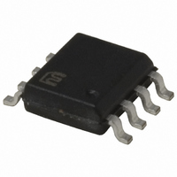
MIC284-3BM TR Micrel Inc, MIC284-3BM TR Datasheet - Page 7

MIC284-3BM TR
Manufacturer Part Number
MIC284-3BM TR
Description
IC SUPERVISOR THERM 2ZONE 8-SOIC
Manufacturer
Micrel Inc
Series
SilentSense™r
Datasheet
1.MIC284-0YM.pdf
(20 pages)
Specifications of MIC284-3BM TR
Function
Temp Monitoring System (Sensor)
Topology
ADC (Sigma Delta), Comparator, Register Bank
Sensor Type
External & Internal
Sensing Temperature
-55°C ~ 125°C, External Sensor
Output Type
I²C™/SMBus™
Output Alarm
Yes
Output Fan
Yes
Voltage - Supply
2.7 V ~ 5.5 V
Operating Temperature
-55°C ~ 125°C
Mounting Type
Surface Mount
Package / Case
8-SOIC (3.9mm Width)
Lead Free Status / RoHS Status
Contains lead / RoHS non-compliant
Other names
MIC284-3BMTR
MIC284-3BMTR
MIC284-3BMTR
mask bit.
/CRIT: Over-temperature events are indicated to external
circuitry via this output. This output is open-drain and may
be wire-OR’ed with other open-drain signals. Most systems
will require a pull-up resistor or current source on this pin.
T1: This pin connects to an off-chip PN diode junction, for
monitoring the junction temperature at a remote location.
The remote diode may be an embedded thermal sens-
ing junction in an integrated circuit so equipped (such
as Intel's Pentium III), or a discrete 2N3906-type bipolar
transistor with base and collector tied together.
Temperature Measurement
The temperature-to-digital converter is built around a switched
current source and an eight-bit analog-to-digital converter.
Each diode's temperature is calculated by measuring its for-
ward voltage drop at two different current levels. An internal
multiplexer directs the MIC284's current source output to either
an internal or external diode junction. The MIC284 uses two’s-
complement data to represent temperatures. If the MSB of a
temperature value is zero, the temperature is zero or positive.
If the MSB is one, the temperature is negative. More detail
on this is given in the "Temperature Data Format" section
below. A “temperature event” results if the value in either of
the temperature result registers (TEMPx) becomes greater
than the value in the corresponding temperature setpoint
register (T_SETx). Another temperature event occurs if and
when the measured temperature subsequently falls below
the temperature hysteresis setting in T_HYSTx.
During normal operation the MIC284 continuously performs
temperature-to-digital conversions, compares the results
against the setpoint registers, and updates the states of /INT,
/CRIT, and the status bits accordingly. The remote zone is
converted first, followed by the local zone. The states of /INT,
/CRIT, and the status bits are updated after each measure-
ment is taken. The remote diode junction connected to T1
may be embedded in an integrated circuit such as a CPU,
ASIC, or graphics processor, or it may be a diode-connected
discrete transistor.
Diode Faults
The MIC284 is designed to respond in a failsafe manner to
hardware faults in the external sensing circuitry. If the con-
September 2005
MIC284
7
nection to the external diode is lost or the sense line (T1) is
shorted to VDD or ground, the temperature data reported
by the A/D converter will be forced to its full-scale value
(+127°C). This will cause a temperature event to occur if
T_SET1 or CRIT1 are set to any value less than 127°C (7F
= 0111 1111
enabled. The temperature reported for the external zone will
remain +127°C until the fault condition is cleared. This fault
detection mechanism requires that the MIC284 complete
the number of conversion cycles specified by Fault_Queue.
The part will therefore require one or more conversion cycles
following power-on or a transition from shutdown to normal
operation before reporting an external diode fault.
Serial Port Operation
The MIC284 uses standard SMBus Write_Byte and Read_Byte
operations for communication with its host. The SMBus
Write_Byte operation involves sending the device’s slave
address (with the R/W bit low to signal a write operation),
followed by a command byte and a data byte. The SMBus
Read_Byte operation is similar, but is a composite write and
read operation: the host first sends the device’s slave address
followed by the command byte, as in a write operation. A
new start bit must then be sent to the MIC284, followed by
a repeat of the slave address with the R/W bit (LSB) set to
the high (read) state. The data to be read from the part may
then be clocked out.
The command byte is eight bits wide. This byte carries the
address of the MIC284 register to be operated upon, and is
stored in the part’s pointer register. The pointer register is
an internal write-only register. The command byte (pointer
register) values corresponding to the various MIC284 register
addresses are shown in Table 2. Command byte values other
than those explicitly shown are reserved, and should not be
used. Any command byte sent to the MIC284 will persist in
the pointer register indefinitely until it is overwritten by another
command byte. If the location latched in the pointer register
from the last operation is known to be correct (i.e., points
to the desired register), then the Receive_Byte procedure
may be used. To perform a Receive_Byte, the host sends
an address byte to select the MIC284, and then retrieves the
data byte. Figures 1 through 3 show the formats for these
procedures.
b
). An interrupt will be generated on /INT if so
Micrel, Inc.
MIC284
h


