LT1123CZ#TR Linear Technology, LT1123CZ#TR Datasheet - Page 9
LT1123CZ#TR
Manufacturer Part Number
LT1123CZ#TR
Description
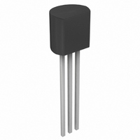
IC LDO REG DRIVER 5V TO-92-3
Manufacturer
Linear Technology
Type
Positive Fixedr
Datasheet
1.LT1123CZ.pdf
(16 pages)
Specifications of LT1123CZ#TR
Number Of Outputs
1
Voltage - Output
5V
Current - Supply
700µA
Operating Temperature
0°C ~ 125°C
Package / Case
TO-92-3 (Standard Body), TO-226
Lead Free Status / RoHS Status
Contains lead / RoHS non-compliant
Voltage - Input
-
Available stocks
Company
Part Number
Manufacturer
Quantity
Price


APPLICATIO S I FOR ATIO
voltage and resistor value. Power dissipation can be
calculated using the following formula:
where:
The worst-case power dissipation in the PNP pass transis-
tor is simply equal to:
where
The thermal resistance of the MJE1123 is equal to:
The PNP will normally be attached to either a chassis or a
heat sink so the actual thermal resistance from junction to
ambient will be the sum of the PNP’s junction to case
thermal resistance and the thermal resistance of the heat
sink or chassis. For nonstandard heat sinks the user will
need to determine the thermal resistance by experiment.
V
V
P
V
I
70°C/W Junction to Ambient (no heat sink)
1.67°C/W Junction to Case
P
OUT
RD
BE
DRIVE
MAX
IN
= Maximum V
= emitter/base voltage of the PNP pass transistor
=
= Maximum I
= (V
(
= voltage at the drive pin of the LT1123
= V
100
V – V – V
1k
10
IN
5
IN
SAT
– V
6
BE
of the drive pin in the worst case
OUT
7
Figure 8. Power in R
U
R
IN
OUT
8
)(I
DRIVE
OUT
9
U
V
IN
10
)
(V)
)
0.25W
0.5W
2
11
12
W
13
D
2W
1W
LT1123 F08
14
15
U
The maximum junction temperature rise above ambient
for the PNP pass transistor will be equal to the maximum
power dissipation times the thermal resistance, junction
to ambient, of the PNP. The maximum operating junction
temperature of the MJE1123 is 150°C. The maximum
operating ambient temperature for the MJE1123 will be
equal to 150°C minus the maximum junction temperature
rise.
The SOT-223 package is designed to be surface mounted.
Heat sinking is accomplished by using the heat spreading
capabilities of the PC board and its copper traces. The
thermal resistance from junction to ambient can be as low
as 50°C/W. This requires a reasonably sized PC board with
at least one layer of copper to spread the heat across the
board and couple it into the surrounding air.
The table below can be used as a guideline in estimating
thermal resistance. Data for the table was generated using
1/16" FR-4 board with 1oz copper foil.
Table 1.
* Tab of device attached to topside copper
For the LT1123 the tab is ground so that plated through
holes can be used to couple the tab both electrically and
thermally to the ground plane layer of the board. This will
help to lower the thermal resistance.
Thermal Limiting
The thermal limit of the LT1123 can be used to protect both
the LT1123 and the PNP pass transistor. This is accom-
plished by thermally coupling the LT1123 to the power
transistor. There are clip type heat sinks available for the
TO-92 package that will allow the LT1123 to be mounted
to the same heat sink as the PNP pass transistor. One
example is manufactured by IERC (part #RUR67B1CB).
The LT1123 should be mounted as close as possible to the
2500 sq. mm
1000 sq. mm
1000 sq. mm
1000 sq. mm
225 sq. mm
100 sq. mm
Topside*
Copper Area
2500 sq. mm
2500 sq. mm
2500 sq. mm
2500 sq. mm
1000 sq. mm
Backside
0
2500 sq. mm
2500 sq. mm
2500 sq. mm
2500 sq. mm
1000 sq. mm
1000 sq. mm
Board Area
(Junction to Ambient)
Thermal Resistance
50°C/W
50°C/W
58°C/W
64°C/W
57°C/W
60°C/W
LT1123
1123fb
9
Related parts for LT1123CZ#TR
Image
Part Number
Description
Manufacturer
Datasheet
Request
R

Part Number:
Description:
Low Dropout Regulator Driver
Manufacturer:
LINER [Linear Technology]
Datasheet:


Part Number:
Description:
CD ROM LINEARVIEW DATASHEETS
Manufacturer:
Linear Technology

Part Number:
Description:
Standalone Linear Li-Ion Battery Charger with Thermal Regulation in ThinSOT
Manufacturer:
Linear Technology Corporation
Datasheet:
Part Number:
Description:
Low noise, high frequency, 8th order linear phase lowpass filter
Manufacturer:
Linear Technology Corporation
Datasheet:
Part Number:
Description:
Manufacturer:
Linear Technology Corporation
Datasheet:
Part Number:
Description:
Manufacturer:
Linear Technology Corporation
Datasheet:
Part Number:
Description:
Manufacturer:
Linear Technology Corporation
Datasheet:
Part Number:
Description:
Manufacturer:
Linear Technology Corporation
Datasheet:
Part Number:
Description:
Manufacturer:
Linear Technology Corporation
Datasheet:
Part Number:
Description:
Manufacturer:
Linear Technology Corporation
Datasheet: