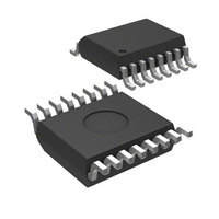
MIC2185BQS Micrel Inc, MIC2185BQS Datasheet

MIC2185BQS
Specifications of MIC2185BQS
Related parts for MIC2185BQS
MIC2185BQS Summary of contents
Page 1
... A skipped pulse mode of operation can be manually set to achieve higher efficiencies at light load conditions. The MIC2185 is available pin SOIC package and 16 pin QSOP package with an ambient temperature operating range from –40°C to 85°C. Ordering Information Standard MIC2185BM MIC2185BQS Typical Application 2.4µ 3. ...
Page 2
Pin Configuration Pin Description Pin Number Pin Name 1 VINA 2 SKIP 3 4 COMP 5 SGND 6 7 EN/UVLO 8 VREF 9 CSH 10 VDD 11 SYNC 12 PGND 13 OUTN 14 OUTP 15 FREQ/2 16 VINP MIC2185 VINA ...
Page 3
Absolute Maximum Ratings (Note 1) Supply Voltage ( .......................................... 15V IN IN Digital Supply Voltage (V ) ............................................ 7V DD Skip Pin Voltage (V ) ....................................–0. SKIP Comp Pin Voltage (V ) ...............................–0. ...
Page 4
Parameter Condition Soft Start Soft Start Current Current Limit Current Limit Threshold Voltage Voltage on CSH to trip current limit Error Amplifier Error Amplifier Gain Current Amplifier Current Amplifier Gain SKIP Input SKIP Threshold SKIP Input Current V SKIP Oscillator ...
Page 5
Typical Characteristics Quiescent Current vs. Temperature (SKIP Mode) 0.8 0.7 0.6 0.5 0 12V 0 QVINA QVINP 0 -40 - ...
Page 6
Oscillator Frequency vs. Input Voltage 422 12V 421 IN DC 420 419 418 417 416 415 414 413 412 INPUT VOLTAGE (V ) INA MIC2185 Oscillator Frequency vs. Temperature ...
Page 7
Functional Diagram V IN EN/UVLO 7 SKIP 2 fs/4 FREQ/2 15 SYNC Osc 11 Correction Ramp SS 3 COMP 4 VREF V REF 8 VDD V 10 Functional Description The MIC2185 is a BiCMOS, switched mode, synchronous boost (step up) ...
Page 8
MOSFET, Q2. Current flows through the MOSFET because its voltage drop is less than diode D1. The MOSFET remains on until the end of the switching cycle. There is another non-overlap time delay between the turn-off of the high side ...
Page 9
Pulling the SKIP pin (pin 2) low will force the controller to operate in PWM mode for all load conditions. Pulling the SKIP pin high will force ...
Page 10
PWM Operation PWM ModeWaveform OUT Switch NodeVoltage (Low Side FE T Drain) 5V/div High Side FET Gate Drive 5V/div Low Side FET Gate Drive 5V/div Inductor Current 1A offset; 0.5A/ RippleVoltage ...
Page 11
V × − R × WINDING V × η IN where the winding resistance of the inductor WINDING R is the on resistance of the low side switching DS(ON) ...
Page 12
Reference, Enable and UVLO Circuits The output drivers are enabled when the following conditions are satisfied: • The VDD voltage (pin 10) is greater than its undervoltage threshold. • The voltage on the Enable pin is greater than the Enable ...
Page 13
Soft Start Soft Start reduces the power supply input surge current at start up by limiting the output voltage rise time. Input surge current occurs when the boost converter charges up the output capacitance. Slowing the output rise time lowers ...
Page 14
Use a ferrite material for the inductor core, which has less core loss than an MPP or iron power core. The significant contributors to power loss at higher output loads are (in approximate order of magnitude): • Resistive on-time ...
Page 15
... SEATING 0.0688 (1.748) PLANE 0.0532 (1.351) MICREL INC. 2180 FORTUNE DRIVE SAN JOSE, CA 95131 USA + 1 (408) 944-0800 TEL This information furnished by Micrel reserves the right to change circuitry and specifications at any time without notification to the customer. Micrel Products are not reasonably be expected to result in personal injury. Life support devices or systems are devices or systems that (a) are intended for surgical implant into the body or (b) support or sustain life, and whose failure to perform can be reasonably expected to result in a signifi ...


