LT1581CT7#PBF Linear Technology, LT1581CT7#PBF Datasheet - Page 3
LT1581CT7#PBF
Manufacturer Part Number
LT1581CT7#PBF
Description
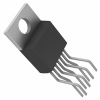
IC LDO REGULATOR 10A ADJ TO220-7
Manufacturer
Linear Technology
Datasheet
1.LT1581CT7PBF.pdf
(12 pages)
Specifications of LT1581CT7#PBF
Applications
Converter, Intel Pentium®
Voltage - Input
1.68 ~ 6 V
Number Of Outputs
1
Voltage - Output
1.25 ~ 4.65 V
Operating Temperature
0°C ~ 125°C
Mounting Type
Through Hole
Package / Case
TO-220-7 (Bent and Staggered Leads)
Primary Input Voltage
6V
Dropout Voltage Vdo
430mV
No. Of Pins
7
Output Current
10A
Operating Temperature Range
0°C To +125°C
Msl
MSL 1 - Unlimited
Termination Type
Through Hole
Rohs Compliant
Yes
Lead Free Status / RoHS Status
Lead free by exemption / RoHS Compliant
Available stocks
Company
Part Number
Manufacturer
Quantity
Price


temperature range, otherwise specifications are at T
PARAMETER
Dropout Voltage (Note 3)
Minimum V
(V
Minimum V
(V
(V
Minimum V
(V
Minimum V
(V
(V
Note 1: Absolute Maximum Ratings are those values beyond which the life
of a device may be impaired.
Note 2: Unless otherwise specified, V
adjustable device, V
Note 3: For the LT1581, dropout is caused by either minimum control
voltage (V
are specified with respect to the output voltage. The specifications represent
the minimum input-to-output voltage required to maintain 1% regulation.
ELECTRICAL CHARACTERISTICS
CONTROL
CONTROL
ADJ
POWER
POWER
ADJ
= 0V)
= 0V)
– V
– V
CONTROL
– V
– V
CONTROL
CONTROL
POWER
POWER
OUT
OUT
OUT
OUT
)
)
)
)
) or minimum power voltage (V
:
:
: LT1581-2.5
: LT1581
ADJ
LT1581-2.5
LT1581
= 0V.
OUT
CONDITIONS
V
V
V
V
V
V
V
V
V
V
V
V
V
V
V
V
V
V
V
V
V
V
V
V
V
V
= V
POWER
POWER
POWER
POWER
POWER
POWER
POWER
POWER
POWER
POWER
CONTROL
CONTROL
CONTROL
CONTROL
CONTROL
CONTROL
CONTROL
CONTROL
CONTROL
CONTROL
CONTROL
CONTROL
CONTROL
CONTROL
CONTROL
CONTROL
SENSE
POWER
= 3.3V, I
= 3.3V, I
= 3.3V, I
= 3.3V, I
= 3.3V, I
= 2.05V, I
= 2.05V, I
= 2.05V, I
= 2.05V, I
= 2.05V, I
. For the LT1581
= 5V, I
= 5V, I
= 5V, I
= 5V, I
= 5V, I
= 5V, I
= 5V, I
= 5V, I
= 2.75V, I
= 2.75V, I
= 2.75V, I
= 2.75V, I
= 2.75V, I
= 2.75V, I
= 2.75V, I
= 2.75V, I
). Both parameters
LOAD
LOAD
LOAD
LOAD
LOAD
LOAD
LOAD
LOAD
LOAD
LOAD
LOAD
LOAD
LOAD
LOAD
LOAD
LOAD
LOAD
LOAD
A
LOAD
LOAD
LOAD
LOAD
LOAD
LOAD
LOAD
LOAD
= 25 C. (Note 2)
= 100mA
= 1A
= 4A, T
= 4A
= 7A, T
= 7A
= 10A, T
= 10A
= 100mA
= 1A
= 4A
= 7A
= 10A
= 100mA
= 1A
= 4A
= 7A
= 10A
= 100mA
= 1A
= 4A, T
= 4A
= 7A, T
= 7A
= 10A, T
= 10A
The
J
J
J
= 25 C
= 25 C
= 25 C
J
J
J
= 25 C
= 25 C
denotes specifications which apply over the full operating
= 25 C
Note 4: For the LT1581 adjustable device the minimum load current is the
minimum current required to maintain regulation. Normally, the current in
the resistor divider used to set the output voltage is selected to meet the
minimum load current requirement.
Note 5: The CONTROL pin current is the drive current required for the
output transistor. This current will track output current with roughly a
1:100 ratio. The minimum value is equal to the quiescent current of the
device.
LT1581/LT1581-2.5
MIN
1.02
1.04
1.06
1.10
1.12
1.02
1.04
1.06
1.10
1.12
0.10
0.13
0.22
0.31
0.43
0.10
0.13
0.22
0.31
0.43
TYP
MAX
1.25
1.27
1.30
1.33
1.35
1.25
1.27
1.30
1.33
1.35
0.20
0.25
0.33
0.37
0.45
0.55
0.63
0.70
0.20
0.25
0.33
0.37
0.45
0.55
0.63
0.70
UNITS
3
V
V
V
V
V
V
V
V
V
V
V
V
V
V
V
V
V
V
V
V
V
V
V
V
V
V
Related parts for LT1581CT7#PBF
Image
Part Number
Description
Manufacturer
Datasheet
Request
R

Part Number:
Description:
CD ROM LINEARVIEW DATASHEETS
Manufacturer:
Linear Technology

Part Number:
Description:
Standalone Linear Li-Ion Battery Charger with Thermal Regulation in ThinSOT
Manufacturer:
Linear Technology Corporation
Datasheet:
Part Number:
Description:
Low noise, high frequency, 8th order linear phase lowpass filter
Manufacturer:
Linear Technology Corporation
Datasheet:
Part Number:
Description:
Manufacturer:
Linear Technology Corporation
Datasheet:
Part Number:
Description:
Manufacturer:
Linear Technology Corporation
Datasheet:
Part Number:
Description:
Manufacturer:
Linear Technology Corporation
Datasheet:
Part Number:
Description:
Manufacturer:
Linear Technology Corporation
Datasheet:
Part Number:
Description:
Manufacturer:
Linear Technology Corporation
Datasheet:
Part Number:
Description:
Manufacturer:
Linear Technology Corporation
Datasheet:
Part Number:
Description:
Manufacturer:
Linear Technology Corporation
Datasheet:
Part Number:
Description:
Dual and Quad, JFET Input Precision High Speed Op Amps
Manufacturer:
Linear Technology Corporation
Datasheet:
Part Number:
Description:
Manufacturer:
Linear Technology Corporation
Datasheet:
Part Number:
Description:
1, 2, 6 and 8 Channel, 10-Bit Serial I/O Data Acquisition Systems
Manufacturer:
Linear Technology Corporation
Datasheet:
Part Number:
Description:
Manufacturer:
Linear Technology Corporation
Datasheet:
Part Number:
Description:
Universal dual filter building block
Manufacturer:
Linear Technology Corporation
Datasheet: