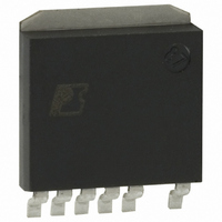
DPA423SN Power Integrations, DPA423SN Datasheet - Page 7

DPA423SN
Manufacturer Part Number
DPA423SN
Description
IC CONV DC-DC DPA SWITCH SPAK
Manufacturer
Power Integrations
Series
DPA-Switch®r
Specifications of DPA423SN
Applications
Converter, Power Over Ethernet and Telecom Applications
Voltage - Input
16 ~ 75 V
Number Of Outputs
1
Voltage - Output
220V
Operating Temperature
-40°C ~ 125°C
Mounting Type
Surface Mount
Package / Case
SPak (5 leads + Tab)
Mounting Style
SMD/SMT
For Use With
596-1195 - KIT REF DES DPA 6.6W DC-DC CONV
Lead Free Status / RoHS Status
Lead free / RoHS Compliant
Available stocks
Company
Part Number
Manufacturer
Quantity
Price
Company:
Part Number:
DPA423SN
Manufacturer:
POWER
Quantity:
15 000
Part Number:
DPA423SN
Manufacturer:
POWER
Quantity:
20 000
Company:
Part Number:
DPA423SN-TL
Manufacturer:
IDT
Quantity:
200
Part Number:
DPA423SN-TL
Manufacturer:
POWER
Quantity:
20 000
(see Figures 4, 7). Limiting DC
prevent transformer saturation due to large load transients in
forward converter applications. DC
threshold was chosen to ensure that the power capability of the
DPA-Switch is not restricted by this feature under normal
operation.
Remote ON/OFF
Remote ON/OFF control describes operation where the IC is
turned on or off for long periods as opposed to the cycle-by-
cycle on/off control, which is described in the Synchronization
section below.
DPA-Switch can be turned on or off by controlling the current
into the LINE-SENSE pin or out from the EXTERNAL CURRENT
LIMIT pin (see Figure 7). This allows easy implementation of
remote ON/OFF control of DPA-Switch in several different ways.
A transistor or an optocoupler output connected between the
EXTERNAL CURRENT LIMIT pin and the SOURCE pin
implements this function with “active-on” (Figures 17, 19 and 21)
while a transistor or an optocoupler output connected between
the LINE-SENSE pin and the CONTROL pin implements the
function with “active-off” (Figures 18, 20 and 22).
When a signal is received at the LINE-SENSE pin or the
EXTERNAL CURRENT LIMIT pin to disable the output through
any of the pin functions such as OV, UV and remote ON/OFF,
DPA-Switch always completes its current switching cycle before
the output is forced off. The internal oscillator is stopped at the
end of the current cycle and stays there as long as the disable
signal exists. When the signal at the above pins changes state
from disable to enable, the internal oscillator starts the next
switching cycle.
The remote ON/OFF feature can be used as a standby or power
switch to turn off the DPA-Switch and keep it in a very low
Figure 6.
www.powerint.com
Synchronization Timing Diagram.
Oscillator
(SAW)
D
MAX
V
L
2 V
0 V
MAX
at higher line voltages helps
MAX
of 33% at the OV
ON
f
SYNC
≥ 128 kHz; t
OFF
OFF
power consumption state for indefi nitely long periods. If the
DPA-Switch is held in remote-off state for longer than 10 μs
(typical), the CONTROL pin goes into the hysteretic mode of
operation. In this mode, the CONTROL pin goes through
alternate charge and discharge cycles between 4.8 V and 5.8 V
(see CONTROL Pin Operation section above) and the IC runs
entirely off the high voltage DC input, but with very low power
consumption (30 mW typical at 48 V with LINE-SENSE and
EXTERNAL CURRENT LIMIT pins open). When the DPA-Switch
is remotely turned on after entering this mode, it will initiate a
normal start-up sequence with soft-start the next time the
CONTROL pin reaches 5.8 V. In the worst case, the delay from
remote on to start-up can be equal to the full discharge/charge
cycle time of the CONTROL pin, which is approximately 36 ms
for a 22 μF CONTROL pin capacitor. This reduced-
consumption remote-off mode can eliminate expensive and
unreliable in-line mechanical switches. It also allows for
microprocessor-controlled turn-on and turn-off sequences that
may be required in certain applications.
Synchronization
In addition to sensing incoming current for OV, UV and remote
ON/OFF, the LINE-SENSE pin also monitors its pin voltage
through a 1 V threshold comparator. A pin voltage below 1 V
turns on DPA-Switch. When the voltage at LINE-SENSE pin
rises beyond 1 V to disable the output, DPA-Switch completes
its current switching cycle before the output is forced off (similar
to remote ON/OFF operation). The internal oscillator is stopped
at the end of the current cycle awaiting the LINE-SENSE pin
voltage to go low to start the next cycle. This allows the use of
the 1 V threshold to synchronize DPA-Switch to an external
signal with a frequency lower than its internal switching
frequency. A transistor or an optocoupler output connected
between the LINE-SENSE pin and the SOURCE pin implements
this function (see Figure 24). Please refer to Figure 6 for the
timing waveforms of synchronization operation.
≤ 7.7 μs; 120 ns ≤ t
t
ON
t
OFF
ON
≤ 2250 ns for f
≤ 3080 ns for f
SYNC
DPA422-426
OSC
OSC
= 400 kHz
= 300 kHz
Time
PI-2762-070501
Rev. S 12/07
7


