LM3677TL-1.82/NOPB National Semiconductor, LM3677TL-1.82/NOPB Datasheet - Page 14
LM3677TL-1.82/NOPB
Manufacturer Part Number
LM3677TL-1.82/NOPB
Description
IC CONV DC/DC SD 1.82V 5USMD
Manufacturer
National Semiconductor
Series
PowerWise®r
Type
Step-Down (Buck)r
Datasheet
1.LM3677LEE-1.2NOPB.pdf
(24 pages)
Specifications of LM3677TL-1.82/NOPB
Internal Switch(s)
Yes
Synchronous Rectifier
Yes
Number Of Outputs
1
Voltage - Output
1.82V
Current - Output
600mA
Frequency - Switching
3MHz
Voltage - Input
2.7 ~ 5.5 V
Operating Temperature
-30°C ~ 85°C
Mounting Type
Surface Mount
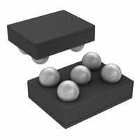
Package / Case
5-MicroSMD
Power - Output
1.18W
Lead Free Status / RoHS Status
Lead free / RoHS Compliant
Other names
LM3677TL-1.82TR


www.national.com
Operation Description
DEVICE INFORMATION
The LM3677, a high-efficiency step-down DC-DC switching
buck converter, delivers a constant voltage from a single Li-
Ion battery and input voltage rails from 2.7V to 5.5V to devices
such as cell phones and PDAs. Using a voltage-mode archi-
tecture with synchronous rectification, the LM3677 has the
ability to deliver up to 600 mA depending on the input voltage
and output voltage, ambient temperature, and the inductor
chosen.
There are three modes of operation depending on the current
required: PWM (Pulse Width Modulation), PFM (Pulse Fre-
quency Modulation), and shutdown. The device operates in
PWM mode at load current of approximately 80 mA or higher,
having a voltage precision of ±2.5% with 90% efficiency or
better. Lighter load current causes the device to automatically
switch into PFM mode for reduced current consumption (I
16 µA typ.) and a longer battery life. Shutdown mode turns off
the device, offering the lowest current consumption
(I
Additional features include soft-start, under voltage protec-
tion, current overload protection, and thermal shutdown pro-
tection. As shown in Figure 1, only three external power
components are required for implementation.
The part uses an internal reference voltage of 0.5V. It is rec-
ommended to keep the part in shutdown until the input voltage
exceeds 2.7V.
CIRCUIT OPERATION
The LM3677 operates as follows. During the first portion of
each switching cycle, the control block in the LM3677 turns
on the internal PFET switch. This allows current to flow from
the input through the inductor to the output filter capacitor and
load. The inductor limits the current to a ramp with a slope of
(V
During the second portion of each cycle, the controller turns
the PFET switch off, blocking current flow from the input, and
then turns the NFET synchronous rectifier on. The inductor
draws current from ground through the NFET to the output
filter capacitor and load, which ramps the inductor current
down with a slope of - V
The output filter stores charge when the inductor current is
high, and releases it when inductor current is low, smoothing
the voltage across the load.
The output voltage is regulated by modulating the PFET
switch-on time to control the average current sent to the load.
The effect is identical to sending a duty-cycle modulated rect-
angular wave formed by the switch and synchronous rectifier
at the SW pin to a low-pass filter formed by the inductor and
output filter capacitor. The output voltage is equal to the av-
erage voltage at the SW pin.
PWM OPERATION
During PWM operation, the converter operates as a voltage-
mode controller with input voltage feed forward. This allows
the converter to achieve good load and line regulation. The
DC gain of the power stage is proportional to the input voltage.
To eliminate this dependence, feed forward inversely propor-
tional to the input voltage is introduced.
While in PWM mode, the output voltage is regulated by
switching at a constant frequency and then modulating the
energy per cycle to control power to the load. At the beginning
of each clock cycle the PFET switch is turned on and the in-
ductor current ramps up until the comparator trips and the
SHUTDOWN
IN
–V
OUT
)/L, by storing energy in a magnetic field.
= 0.01 µA (typ.).
OUT
/L.
Q
=
14
control logic turns off the switch. The current limit comparator
can also turn off the switch in case the current limit of the
PFET is exceeded. Then the NFET switch is turned on and
the inductor current ramps down. The next cycle is initiated
by the clock turning off the NFET and turning on the PFET.
Internal Synchronous Rectification
While in PWM mode, the LM3677 uses an internal NFET as
a synchronous rectifier to reduce rectifier forward voltage
drop and associated power loss. Synchronous rectification
provides a significant improvement in efficiency whenever the
output voltage is relatively low compared to the voltage drop
across an ordinary rectifier diode.
Current Limiting
A current limit feature allows the LM3677 to protect itself and
external components during overload conditions. PWM mode
implements current limiting using an internal comparator that
trips at 1220 mA (typ.). If the output is shorted to ground the
device enters a timed current limit mode where the NFET is
turned on for a longer duration until the inductor current falls
below a low threshold, ensuring inductor current has more
time to decay, thereby preventing runaway.
PFM OPERATION
At very light loads, the converter enters PFM mode and op-
erates with reduced switching frequency and supply current
to maintain high efficiency.
The part will automatically transition into PFM mode when ei-
ther of the following conditions occurs for a duration of 32 or
more clock cycles:
level, (Typically I
A.
B.
The NFET current reaches zero.
The peak PMOS switch current drops below the I
FIGURE 6. Typical PWM Operation
MODE
< 75 mA + V
IN
/55Ω ).
30008480
MODE
Related parts for LM3677TL-1.82/NOPB
Image
Part Number
Description
Manufacturer
Datasheet
Request
R

Part Number:
Description:
IC CONV DC/DC ADJ 5-USMD
Manufacturer:
National Semiconductor
Datasheet:
Part Number:
Description:
IC CONV DC/DC 1.2V 5-USMD
Manufacturer:
National Semiconductor
Datasheet:
Part Number:
Description:
IC CONV DC/DC STEPDOWN 5MICROSMD
Manufacturer:
National Semiconductor
Datasheet:
Part Number:
Description:
IC CONV DC/DC STEPDOWN 5MICROSMD
Manufacturer:
National Semiconductor
Datasheet:
Part Number:
Description:
IC CONV DC/DC STEPDOWN 5MICROSMD
Manufacturer:
National Semiconductor
Datasheet:
Part Number:
Description:
IC CONV DC-DC 600MA SD 5USMD
Manufacturer:
National Semiconductor
Datasheet:
Part Number:
Description:
IC CONV DC/DC STEPDOWN 5MICROSMD
Manufacturer:
National Semiconductor
Datasheet:

Part Number:
Description:
BOARD EVALUATION LM3677TL-1.8
Manufacturer:
National Semiconductor
Datasheet:

Part Number:
Description:
IC, BUCK, REG, ADJ, 5USMD
Manufacturer:
National Semiconductor
Datasheet:
Part Number:
Description:
National Semiconductor [8-Bit D/A Converter]
Manufacturer:
National Semiconductor
Datasheet:
Part Number:
Description:
National Semiconductor [Media Coprocessor]
Manufacturer:
National Semiconductor
Datasheet:
Part Number:
Description:
Digitally Controlled Tone and Volume Circuit with Stereo Audio Power Amplifier, Microphone Preamp Stage and National 3D Sound
Manufacturer:
National Semiconductor
Datasheet:
Part Number:
Description:
Digitally Controlled Tone and Volume Circuit with Stereo Audio Power Amplifier, Microphone Preamp Stage and National 3D Sound
Manufacturer:
National Semiconductor
Datasheet:
Part Number:
Description:
AC97 Rev 2 Codec with Sample Rate Conversion and National 3D Sound
Manufacturer:
National Semiconductor
Part Number:
Description:
Manufacturer:
National Semiconductor
Datasheet: